Last updated on March 23rd, 2024 at 05:46 pm
This is a popular NPN bipolar junction transistor used in low power and current, medium voltage applications. It is widely used for low-power amplification and switching.
2N3904 is complementary to 2N3906 PNP bipolar junction transistor.

It has a current rating of 200 mA, a voltage rating of 40 V, and a power rating of 625 mW. And provides a current gain of 100 when the current of 10 mA flows through the collector. 2N3N04 is popular due to its high gain and low saturation voltage.
Note: The 2N3904 transistor was first manufactured by Motorola.
Table of Contents
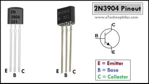
2N3904 Transistor Pinout

The Pinout of the transistor has three pins: emitter, base, and collector respectively from left to right(flat side with the leads pointed downward).
Specifications
| Feature | Value |
| Type | NPN |
| Package(THT) | TO-92 |
| Collector-Base Voltage | 60 V |
| Collector-Emitter Voltage: | 40 V |
| Emitter-Base Voltage: | 6 V |
| Collector Current: | 0.2 A |
| Collector Dissipation – | 0.625 W |
| DC Current Gain (hFE) | 100 to 300 |
| Transition Frequency | 300 MHz |
| Noise | 5 dB |
| Junction Temperature Range | 55 to +150 °C |
Equivalent
Below is the list of popular transistors that can be used as a replacement for 2N3904.
Datasheet
This transistor is available in Through-hole and a wide variety of SMD packages(SOT23, SOT223, etc) with TO-92 being the most popular one. 2N3904 is called MMBT3904 in SOT23 or SMD package.
Given below is the datasheet of the 2N3904 transistor in the TO-92 package:
Electrical characteristics, current-voltage ratings, and physical dimensions of this transistor are given in detail in this datasheet.
Given below is the datasheet of 2N3904 transistor(MMBT3904) in the SOT23 package:
Where to buy?

2N3904 TO-92 Package dimensions
Given below is the image of the 2N3904 transistor TO-92 package dimensions. All the dimensions are in mm.

2N3904-based electronics projects:
Using 2N3904 Transistor as a switch:

In the circuit diagram given above, the 2N3904 transistor is used as a switch to turn ON/OFF an LED connected at the collector terminal. The complete circuit is powered via a 5 V supply.
The base of the transistor is biased using a 10 K Ohm resistor(R3) in parallel to the 1 K Ohm resistor(R2) plus base-emitter junction resistance(in series). OR R3 || ( R2+RBE ). Proper biasing of the base ensures adequate base current to turn ON the transistor.
A resistor of 220 Ohm is connected between the load(LED) and the collector terminal to protect the LED from overcurrent. The required resistor value can be easily calculated using Ohm’s law.
When the switch is open, the base of the transistor is not biased. And no current flows to the base of the transistor. Due to this, 2N3904 remains in the cut-off state and the LED does not glow.
When the switch is closed, the base of the transistor is biased, and current flows to the base of the transistor. Due to this biasing current, it goes to the saturation state and the LED turns ON.
FAQs
What is the function of the 2N3904 transistor?
It is used for low-power amplification and switching in electronic circuits.
What is the voltage range of a 2N3904?
Voltage range of approximately 40 to 60 volts when used in common electronic circuits.