Last updated on March 19th, 2024 at 12:46 pm
FQP30N06L is an N-channel enhancement mode power field effect transistor and is a logic-level Mosfet. This means it can turn ON fully by using the logic level(3.3V OR 5V) of a microcontroller.
This Mosfet is quite popular due to its low on-state resistance, superior switching performance, and its ability to withstand high energy pulse in the avalanche and commutation mode.

FQP30N06L Mosfet has voltage, current, and power dissipation ratings of 60 V, 32 A, and 79 watts respectively at 25 degrees Celsius room temperature. And has a low Drain to source resistance(RDS(ON)) of 0.035 ohms at a maximum Gate threshold voltage of 10 V.
You can use it in switch-mode power supply circuits, audio amplifiers, and for dc motor control using Arduino or a similar microcontroller.
This Mosfet is commonly used in low-voltage applications such as automotive, DC/DC converters, and high-efficiency switching for power management in portable and battery-operated products.
Table of Contents
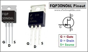
FQP30N06L Mosfet Pinout
Just like any other Mosfet, the FQP30N06L pinout has three pins: Gate, Drain, and Source respectively from left to right(flat side with the leads pointed downward).

Datasheet
Download the FQP30N06L datasheet from here.
Engineers and hobbyists can make use of the Absolute maximum ratings, thermal characteristics, switching characteristics, and their graphs to build accurate and robust circuits. All such details are given in the datasheet above.
Technical specifications
| Feature | Value |
| Type | N Channel |
| Package | TO-220 |
| Drain-Source voltage | 60 V |
| Gate-Source voltage | 20 V |
| Gate Threshold voltage | 2.5 V |
| Drain current max. | 32 A |
| Max. Junction temperature | 175 °C |
| Max. RDS(ON) | 0.045 Ohm |
| Total Gate Charge | 15 nC |
| Max. power dissipation | 79 W |
FQP30N06L equivalent
Given below is the list of similar/Equivalent FQP30N06L Mosfets:
- FQP10N60
- FQP10N60C
- FQP10N60CF
- FQP11N40
- FQP11N40C
- FQP11N50CF
- FQP10N20
- FQP10N20C
How to use FQP30N06L with Arduino?
It is a logic level Mosfet, meaning it can turn ON fully(almost) by using the logic level(3.3V OR 5V) of a microcontroller.

The datasheet of FQP30N06L shows that it has RDS(ON) or Static drain-source On-Resistance of 0.045 ohms(max.) at VGS of 5V and drain current of 16 A. This simply means that if 5 V is applied at the Gate of this Mosfet, it can switch a load up to 16 Amps with a drain to source resistance of 0.035 ohms.

The VGS vs ID graph given in the datasheet shows that at Gate to source voltage of 3 V, the Mosfet conducts more than 10 A easily, and at 5 V Vgs it can conduct more than 30 A. So this mosfet can be connected directly to the output pin of Arduino to control the external load. Because digital pins of Arduino can output 5 V maximum.
But keep in mind that a load of 30A will cause a high drain to source resistance RDSon of the Mosfet. And the larger the value of RDS, the higher the (power) loss i.e, I2R loss.
DC motor speed control using FQP30N06L and Arduino :
In this example, a DC motor speed is controlled using this Mosfet with Arduino. You can use any other load like a lamp or solenoid in place of the motor.
A potentiometer is used to set the speed of the dc motor. Arduino takes analog input from the potentiometer and sets the voltage across the load according to it.

To use it with Arduino follow these steps:
- Connect the Arduino with the Mosfet using the required components as shown in the circuit diagram above
- Load can be a Motor, a lamp, solenoid etc.
- Gate of the Mosfet is connected to the Digital PWM pin 3 of the Arduino UNO here, you can connect it to any other PWM pin according to the Load PWM frequency OR switching frequency requirements.
To know more about Arduino PWM frequency change, read this article.
- Upload the code given below to your Arduino board:
/*
  DC Motor speed control using FQP30N06L with Arduino and potentiometer
*/

int motorPin = 3;       // the pin that the motor is attached to
int pot = A0;     // potentiometer is connected to analog pin 0

void setup()  {
  // declare pin 3 and A0 to be an output and input respectively:
  pinMode(motorPin, OUTPUT);
  pinMode(pot, INPUT);
  Serial.begin(9600);          //  setup serial
}

int getPotValue() {
  int potAnValue = analogRead(pot);    // read the input pin
  int potPWMValue = map(potAnValue, 0, 1023, 0, 255); // mapping to get 0 to 255
  if (potPWMValue < 102)// below PWM value 102(Vgs=2v) use PWM value 0 to avoid rough run
    potPWMValue = 0;
  else
    potPWMValue = min(potPWMValue, 255);  // if above 255 somehow, use 255 max
  return potPWMValue;
}

// the loop routine runs over and over again forever:
void loop()  {
  // set the PWM value on pin 3 for motor speed control
  analogWrite(motorPin, getPotValue());
  // print out getPotValue to serial monitor
  Serial.println(getPotValue());
  // 20 ms delay (can add noticible delay if over 200ms)
  delay(20);
}
Now, you should be able to control the load current using this Mosfet.
Physical dimensions
FQP30N06L is 3 cm in length and 1 cm wide.

Uses and applications:
- Switch mode power supply circuits,
- In audio amplifiers
- For DC motor control using Arduino or similar microcontroller.
- DC/DC converters
Thanks for sharing. Can I control negative loads like a bulb lamp connected to the negative side of a symmetric psu ? Thank you
Hi Gibran,
Can you please elaborate on what you tryna do? Any schematic or something?
I think this is a great article. I am trying to bread board your circuit.
Any chance you would be willing to comment on my arduino forum thread?
https://forum.arduino.cc/t/how-to-control-power-from-a-dc-bus-to-a-hbridge/893420/31
Hi Brian,
I went through the Arduino forum thread shared by you. I can certainly help you out there. But there are a couple of things I would like you to try first:
1. First and foremost try the circuit given here, so that we can be sure about the MOSFET health. Double-check your circuit connections, maybe you are connecting the Mosfet pins incorrectly(check the pinout).
2. You can power the Arduino independently(through USB), you don’t have to connect the battery to it. Just make sure that the Ground of all the devices is connected together. If you want to power the Arduino through Battery, then connect its +Ve terminal to the Vin pin of Arduino(not +5V, this can damage the board)
3. Use the program given here. Even if you use an LED in place of the Motor(use a 1K ohm resistor), it will still work.
Do get back to us, if you face any issues.