Last updated on June 7th, 2025 at 05:37 pm
A Passive Infrared (PIR) Sensor is one of the most commonly used motion detection sensors in home automation, security systems, and robotics. It detects the presence of humans or animals based on infrared (IR) radiation emitted by their bodies. In this tutorial, we will explore how a PIR sensor like HC-SR501 works and how to interface it with an Arduino by making a motion-activated light bulb project.
What is a PIR Sensor?
A PIR (Passive Infrared) Sensor detects motion by measuring changes in infrared radiation in its field of view. Since all objects emit some level of infrared radiation, especially warm bodies like humans and animals, the PIR sensor can identify movement based on variations in IR levels.
Table of Contents
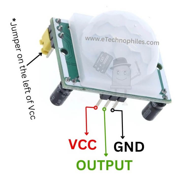
Pinout of HC-SR501
Key specs of HC-SR501
Below is a concise table detailing the typical key specifications of the HC-SR501 PIR motion sensor module. Note that actual values can vary slightly depending on the specific manufacturer and production batch.
| Parameter | Typical Specification |
|---|---|
| Operating Voltage | 5 V to 20 V DC (commonly powered at 5 V or 9–12 V) |
| Current Consumption | ~50 µA to 100 µA (standby) |
| Output Signal | Digital: HIGH ~3.3 V, LOW ~0 V (compatible with most 3.3 V or 5 V MCUs) |
| Detection Range | up to 7 m (adjustable via sensitivity potentiometer) |
| Detection Angle (FOV) | ~110° to 120° |
| Time Delay Range | ~0.3 s to 300 s (adjustable via onboard “Time” potentiometer) |
| Trigger Modes | – Repeatable Trigger (H): Output stays HIGH as long as motion is detected – Non-Repeatable Trigger (L): Output goes HIGH and remains HIGH for the set delay, ignoring further motion until the delay expires |
| Warm-Up Time | 30–60 s after power-up for stable operation |
| Operating Temperature | Typically -15 °C to +70 °C (some variants may differ) |
| Module Dimensions | ~32 mm × 24 mm PCB (lens dome protrudes above the board) |
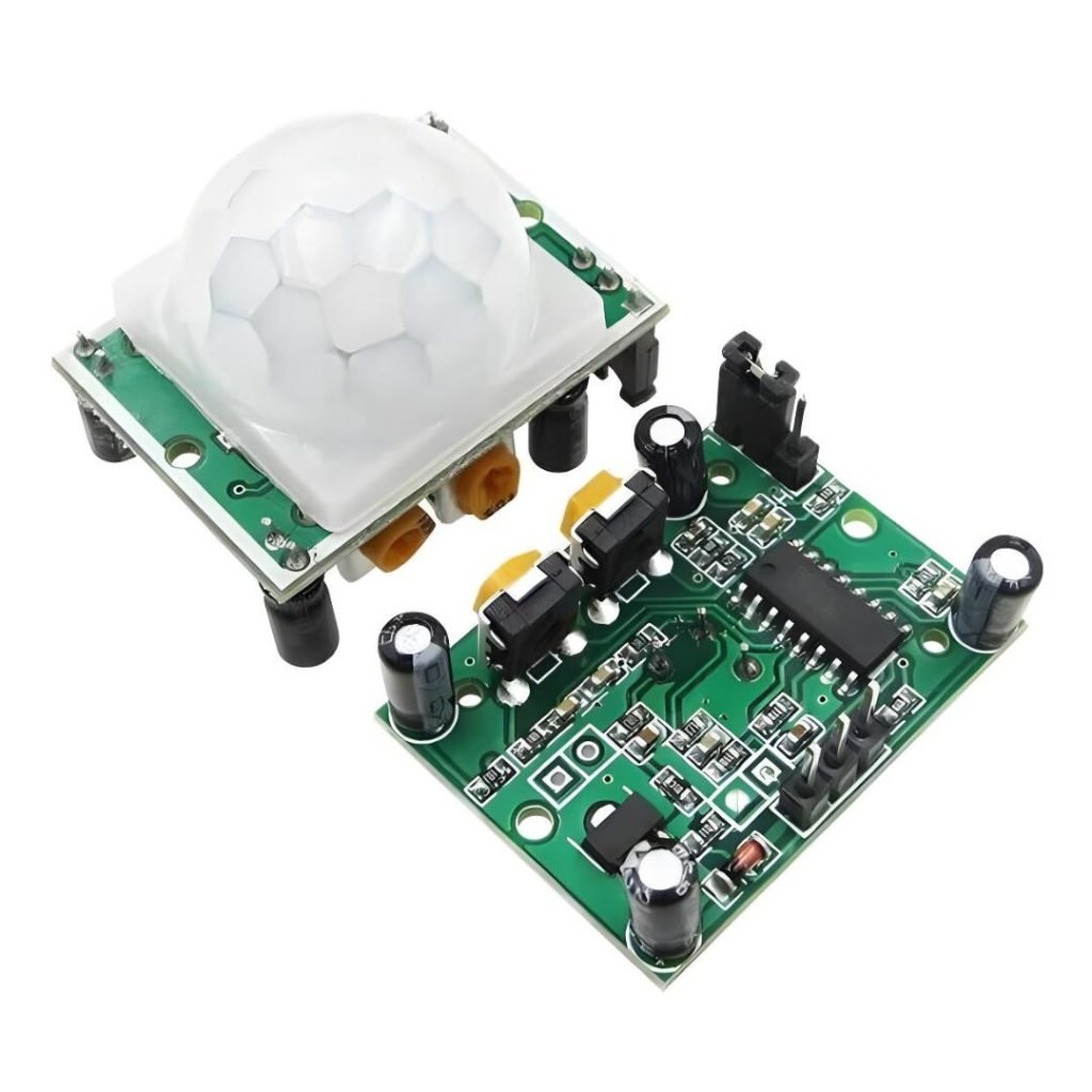
Construction of HC-SR501 PIR Module
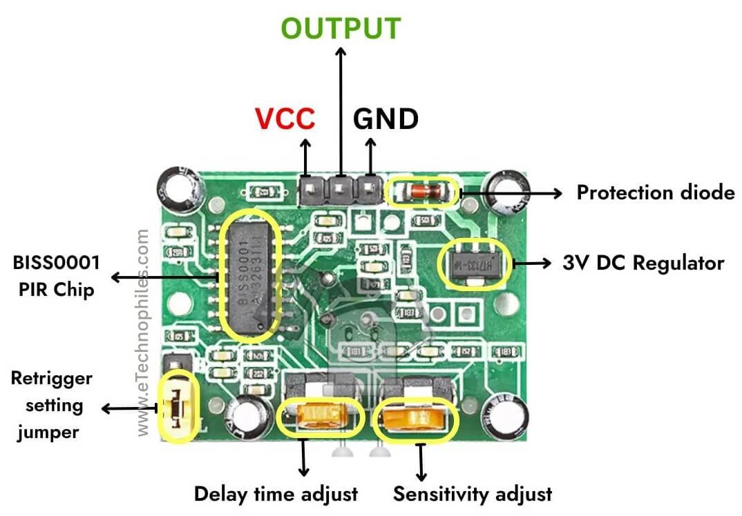
The PIR motion sensor module consists of several key components, each contributing to its functionality:
BISS0001 PIR Chip: This is the core integrated circuit (IC) responsible for processing signals from the PIR sensor. It amplifies, filters, and interprets the detected infrared radiation changes to determine motion.
PIR Sensor: The small metal canister positioned at the module’s center contains the pyroelectric sensor, which detects infrared radiation. This sensor is typically covered by a Fresnel lens, which enhances detection by focusing infrared signals from different angles onto the sensor.
3V DC Regulator (HT7133-1): The onboard voltage regulator ensures a stable 3V supply to the BISS0001 chip, allowing the module to operate reliably even with varying input voltages.
Protection Diode: A diode is included to prevent damage from accidental reverse polarity connections, safeguarding the circuit against incorrect power supply wiring.
Vcc: Connects to the power supply (commonly 5V or 12V).
Output: Generates a HIGH signal when motion is detected and LOW otherwise.
GND: Ground reference for the circuit.
Retrigger Setting Jumper: A configurable jumper is present to control the retrigger mode:
H (High): Retrigger enabled – The output remains HIGH as long as motion is detected.
L (Low): Retrigger disabled – The output remains HIGH for a fixed duration after motion is detected, regardless of continued movement.
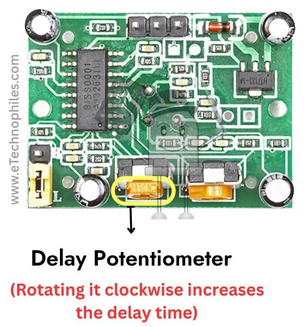
Delay Time Adjustment Potentiometer: This variable resistor allows adjustment of how long the output stays HIGH after motion detection. It fine-tunes the duration before the sensor resets.
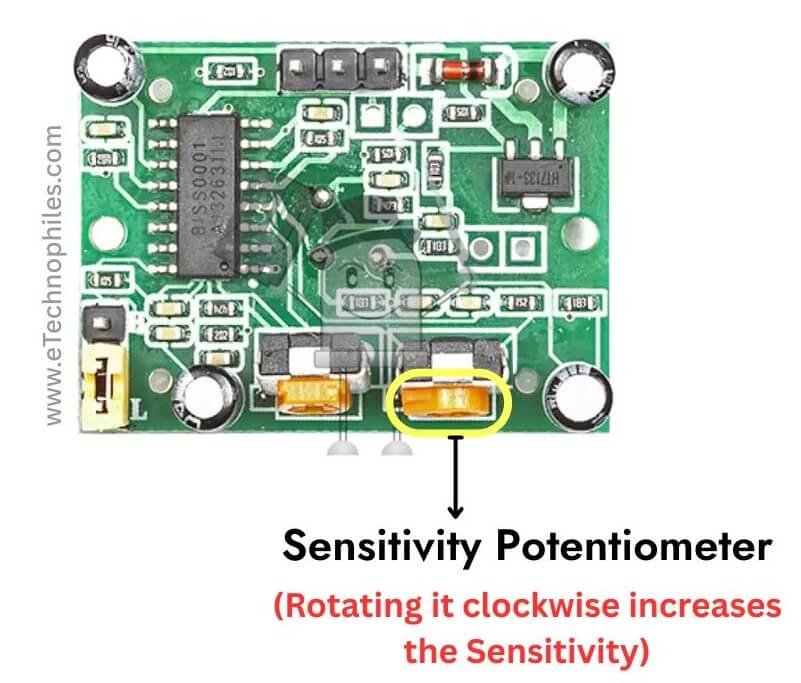
Sensitivity Adjustment Potentiometer: This potentiometer modifies the detection range, determining the level of infrared change needed to trigger the sensor.
How Does a PIR Sensor Work?
The HC-SR501 PIR motion sensor utilizes a pyroelectric sensor to detect changes in infrared radiation emitted by objects. When a warm object moves within its range, the sensor registers a shift in infrared levels.
This change triggers the BISS0001 chip, which processes the signal and generates a high output signal on the designated pin. The module features adjustable sensitivity and delay time, controlled by onboard potentiometers, allowing users to fine-tune its operation.
A retrigger jumper enables customization of the sensor’s behavior after initial detection. Power is supplied through Vcc and GND pins, with an integrated 3V regulator ensuring stable operation. A protection diode safeguards the circuit from reverse polarity.
The module’s design, incorporating a Fresnel lens (typically included but not visible in the provided image) to focus infrared radiation, enables effective motion detection within a specified range. This makes it a versatile and widely used component in various applications, from security systems to automated lighting.
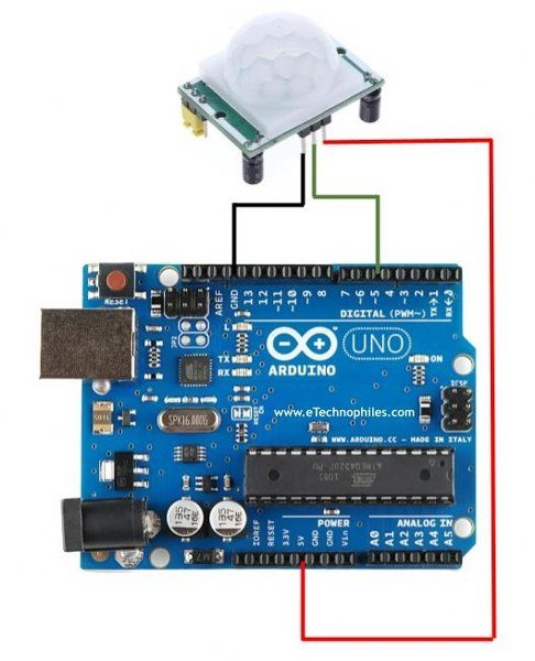
PIR sensor with Arduino
To interface this sensor with your Arduino, follow these steps:
OUT pin to digital pin 3.
- VCC pin to 5V pin on Arduino
- GND pin to GND
- OUT pin to digital pin 3.
2. Upload this program to your Arduino board.
const int PIR_PIN = 3;       // PIR sensor OUT pin connected to digital pin 3
int PIR_STATE = LOW;         // Initial state of PIR sensor
int val = 0;                 // Variable to store the read value

void setup() {
  pinMode(PIR_PIN, INPUT);
  Serial.begin(9600);        // Start serial communication
}

void loop() {
  val = digitalRead(PIR_PIN);   // Read the state of the PIR sensor

  if (val == HIGH) {
    if (PIR_STATE == LOW) {
      Serial.println("Motion detected");
      PIR_STATE = HIGH;
    }
  } else {
    if (PIR_STATE == HIGH) {
      Serial.println("No motion is detected");
      PIR_STATE = LOW;
    }
  }

  delay(500);  // Small delay to avoid flooding the serial monitor
}
Note: The variable PIR_STATE helps prevent repeated messages if the state hasn’t changed.
3. Wait for at least 30 seconds before taking any readings. The PIR module needs time to warm up.
4. Open the serial monitor on your Arduino IDE.
5. You will get readings like this on your monitor:
If there’s a motion- the serial monitor prints, “Motion detected”. If there’s no motion, it prints, “No motion is detected”.
6. Using a screwdriver, adjust the settings of the ‘sensitivity potentiometer’. Turning it clockwise makes it more sensitive i.e., the detection distance increases. You can adjust this up to 7 meters!
7. Similarly, you can adjust the ‘delay or time potentiometer’ to control the hold time – the duration that the sensor’s output pin stays HIGH after it detects motion. Clockwise increases the time delay, for example, if set to 3 seconds, the sensor will output 1 or HIGH for three seconds after detecting a motion. You can set this up to 5 minutes or 300 seconds!
Motion-activated LED bulb project
Now let’s make a project, which recognizes the movement of a person and turns ON/OFF an AC light bulb accordingly.
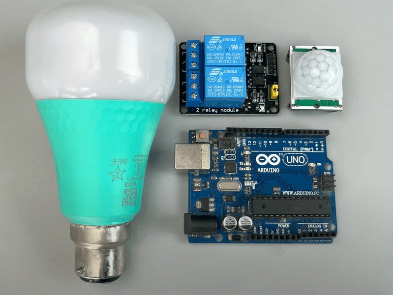
Components required
For this project, you will need:
- Arduino UNO
- PIR sensor
- 2 Channel relay module
- A.C LED Bulb
- Jumper wires
- Electric wires
- Breadboard
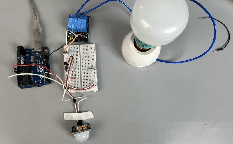
Circuit diagram
Connect the components as shown below:

Program
#define PIR_PIN 5     // Digital pin for PIR sensor
#define RELAY_PIN 12  // Digital pin for relay

unsigned long motionTimeout = 3000;  // Time in milliseconds to wait before turning off relay
unsigned long lastMotionTime = 0;

void setup() {
  // Initialize serial communication
  Serial.begin(9600);

  // Configure PIR sensor pin as input
  pinMode(PIR_PIN, INPUT);

  // Configure relay pin as output
  pinMode(RELAY_PIN, OUTPUT);
  digitalWrite(RELAY_PIN, HIGH);  // Ensure relay is off initially (reverse logic)

  Serial.println("PIR Sensor and Relay Control Initialized");
}

void loop() {
  // Read PIR sensor state
  int pirState = digitalRead(PIR_PIN);

  if (pirState == HIGH) {
    // Motion detected: Turn ON the relay and reset the timer
    digitalWrite(RELAY_PIN, LOW);  // Turn ON relay (reverse logic)
    lastMotionTime = millis();     // Update the last motion detection time
    Serial.println("Motion detected: Relay ON");
  } else {
    // No motion: Check if timeout has elapsed
    if (millis() - lastMotionTime > motionTimeout) {
      digitalWrite(RELAY_PIN, HIGH);  // Turn OFF relay (reverse logic)
      Serial.println("No motion: Relay OFF");
    }
  }

  // Small delay for stability
  delay(100);
}
Code explained
#define PIR_PIN 5     // Digital pin for PIR sensor
#define RELAY_PIN 12  // Digital pin for relay

unsigned long motionTimeout = 3000;  // Time in milliseconds to wait before turning off relay
unsigned long lastMotionTime = 0;- PIR_PIN (pin 5) is assigned to read the PIR sensor output.
- RELAY_PIN (pin 12) is assigned to control the relay module.
- motionTimeout = 3000: Defines a 3-second timeout after the last motion detection before turning off the relay.
- lastMotionTime: Stores the timestamp of the last detected motion.
void setup() {
  // Initialize serial communication
  Serial.begin(9600);

  // Configure PIR sensor pin as input
  pinMode(PIR_PIN, INPUT);

  // Configure relay pin as output
  pinMode(RELAY_PIN, OUTPUT);
  digitalWrite(RELAY_PIN, HIGH);  // Ensure relay is off initially (reverse logic)

  Serial.println("PIR Sensor and Relay Control Initialized");
}- Serial.begin(9600); → Initializes serial communication for debugging.
- pinMode(PIR_PIN, INPUT); → Configures the PIR sensor pin as an input.
- pinMode(RELAY_PIN, OUTPUT); → Configures the relay pin as an output.
- digitalWrite(RELAY_PIN, HIGH); → Turns the relay off initially (reverse logic is used, meaning LOW = ON, HIGH = OFF).
- A message is printed to the Serial Monitor to indicate initialization.
void loop() {
  // Read PIR sensor state
int pirState = digitalRead(PIR_PIN);- Reads the state of the PIR sensor (HIGH if motion is detected, LOW otherwise).
  if (pirState == HIGH) {
    // Motion detected: Turn ON the relay and reset the timer
    digitalWrite(RELAY_PIN, LOW);  // Turn ON relay (reverse logic)
    lastMotionTime = millis();     // Update the last motion detection time
    Serial.println("Motion detected: Relay ON");
}- If the PIR sensor detects motion (pirState == HIGH):
The relay is turned ON (LOW due to reverse logic).
The timestamp (lastMotionTime) is updated using millis().
A message is printed to indicate that motion has been detected. the PIR sensor detects motion (pirState == HIGH):- The relay is turned ON (
LOWdue to reverse logic). - The timestamp (lastMotionTime) is updated using millis().
- A message is printed to indicate that motion has been detected.
- The relay is turned ON (
  else {
    // No motion: Check if timeout has elapsed
    if (millis() - lastMotionTime > motionTimeout) {
      digitalWrite(RELAY_PIN, HIGH);  // Turn OFF relay (reverse logic)
      Serial.println("No motion: Relay OFF");
    }
}- If no motion is detected (pirState == LOW):
- The code checks if the timeout (3 seconds) has elapsed since the last motion detection.
- If more than 3 seconds (motionTimeout) have passed since the last motion:
- The relay is turned OFF (HIGH due to reverse logic).
- A message is printed indicating the relay has been turned off.
  // Small delay for stability
delay(100);- A 100ms delay is added to stabilize sensor readings and avoid rapid relay switching.