A color sensor is widely used in various applications, including industrial automation, color detection in printing, and robotics. It detects the color of an object and provides an output signal that can be processed by a microcontroller. In this tutorial, we will explore how a color sensor works and how to interface it with an Arduino to create some cool projects.
What is a color sensor?
A color sensor detects the color of an object by analyzing the intensity of red, green, and blue (RGB) light reflected from it. It typically includes a photodetector, an optical filter, and a signal processing circuit that provides a digital or analog output representing the detected color.
There are many popular color sensors available in the market, such as TCS3200, TCS230, and TCS34725. In this tutorial, I am going to use TCS34725(more advanced and accurate) with Arduino.
Table of Contents
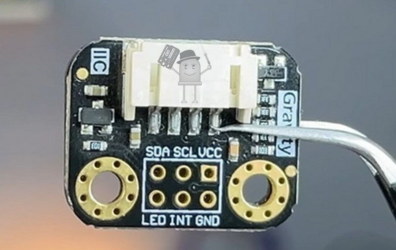
TCS34725 color sensor pinout
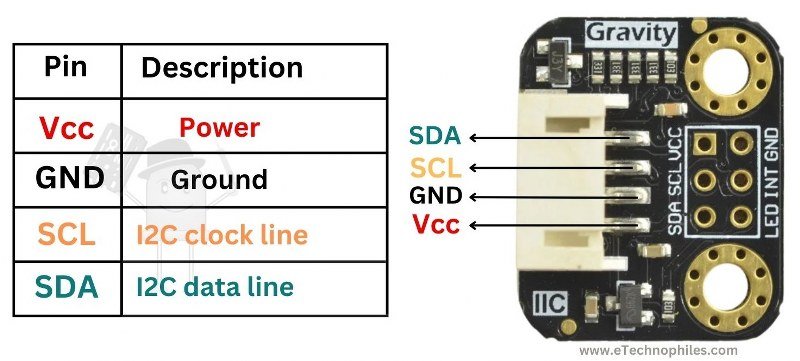
A typical TCS34725 color sensor module consists of the following pins:
- VIN – Power supply (3.3V to 5V)
- GND – Ground
- SDA – I2C data line (connects to Arduino’s A4)
- SCL – I2C clock line (connects to Arduino’s A5)
- LED – Controls the onboard white LED (can be connected to GND to disable)
- INT – Interrupt output (optional, for advanced applications)
Key specifications of the color sensor
Below is a table with the specifications of the TCS34725 color sensor:
| Parameter | Specification |
|---|---|
| Operational Voltage Range | 3.3V – 5V |
| Operational Current | 0.2 – 60 mA |
| Detectable Colors | Red, Green, Blue |
| Output Type | I2C Digital Output |
| IR Blocking Filter | Yes |
| White LED | Integrated for uniform lighting |
| Integration Time | Programmable (2.4 ms – 700 ms) |
Construction
The TCS34725 color sensor consists of two main parts:
- Photodetector and IR-Blocking – The sensor has four photodiodes that measure red, green, blue, and clear (ambient) light intensity. The IR-blocking filter improves color accuracy by eliminating infrared interference.
- Electronic Module – The electronic module processes the detected light signals and converts them into an I2C-compatible output. It includes:
- TCS34725 Sensor Chip – A high-sensitivity RGB color sensor with an IR filter.
- ADC (Analog-to-Digital Converter) – Converts light intensity into digital values.
- I2C Communication Interface – Allows easy data transmission to microcontrollers.
- Onboard White LED – Provides a uniform light source for consistent color detection.
How does a color sensor work?
A color sensor detects and measures the intensity of red, green, and blue (RGB) light reflected from an object. It consists of a photodetector array that captures light and a white LED to ensure consistent illumination.
When light hits an object, different wavelengths are absorbed and reflected based on the object’s color. The sensor receives the reflected light and converts it into electrical signals, which are processed to determine the RGB composition.
An onboard ADC (Analog-to-Digital Converter) processes these signals and sends the data to a microcontroller, which interprets the color values. The microcontroller can then use this information to trigger specific actions, such as sorting objects by color, adjusting display settings, or controlling lighting effects.
RGB color detector project
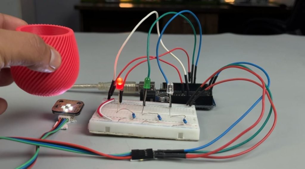
Now, let’s build a system where an RGB LED changes color based on the detected object color.
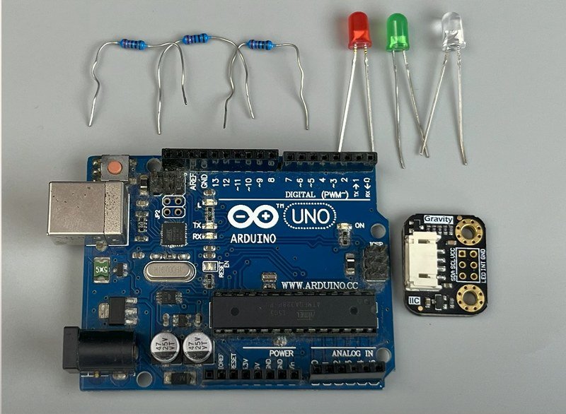
Components required:
- Arduino UNO
- TCS34725 Color Sensor Module
- RGB LED or Individual LEDs (Red, Green, Blue)
- Jumper Wires
- External Power Supply (if required)
Circuit diagram:

Program
#include <Wire.h>
#include "Adafruit_TCS34725.h"

// Pins for RGB LEDs
#define RED_LED_PIN 3
#define GREEN_LED_PIN 5
#define BLUE_LED_PIN 6

Adafruit_TCS34725 tcs = Adafruit_TCS34725(TCS34725_INTEGRATIONTIME_50MS, TCS34725_GAIN_4X);

void setup() {
  Serial.begin(9600);

  if (!tcs.begin()) {
    Serial.println("No TCS34725 found ... check your connections");
    while (1)
      ;
  }

  // Initialize LED pins as output
  pinMode(RED_LED_PIN, OUTPUT);
  pinMode(GREEN_LED_PIN, OUTPUT);
  pinMode(BLUE_LED_PIN, OUTPUT);

  // Turn off all LEDs initially
  digitalWrite(RED_LED_PIN, LOW);
  digitalWrite(GREEN_LED_PIN, LOW);
  digitalWrite(BLUE_LED_PIN, LOW);
}

void loop() {
  uint16_t r, g, b, c;
  tcs.getRawData(&r, &g, &b, &c);

  // Normalize RGB values using clear channel (luminance)
  float red = r / (float)c * 255.0;
  float green = g / (float)c * 255.0;
  float blue = b / (float)c * 255.0;

  // Ensure values stay in bounds
  red = constrain(red, 0, 255);
  green = constrain(green, 0, 255);
  blue = constrain(blue, 0, 255);

  Serial.print("R:");
  Serial.print((int)red);
  Serial.print(" G:");
  Serial.print((int)green);
  Serial.print(" B:");
  Serial.println((int)blue);

  // Calculate differences between RGB values
  float diffRG = abs(red - green);
  float diffRB = abs(red - blue);
  float diffGB = abs(green - blue);

  // Turn off LEDs if differences are within the range of 30
  if (diffRG <= 50 && diffRB <= 50 && diffGB <= 50) {
    digitalWrite(RED_LED_PIN, LOW);
    digitalWrite(GREEN_LED_PIN, LOW);
    digitalWrite(BLUE_LED_PIN, LOW);
  } else {
    // Determine the dominant color and turn on the corresponding LED
    if (red > green && red > blue) {
      digitalWrite(RED_LED_PIN, HIGH);
      digitalWrite(GREEN_LED_PIN, LOW);
      digitalWrite(BLUE_LED_PIN, LOW);
    } else if (green > red && green > blue) {
      digitalWrite(RED_LED_PIN, LOW);
      digitalWrite(GREEN_LED_PIN, HIGH);
      digitalWrite(BLUE_LED_PIN, LOW);
    } else if (blue > red && blue > green) {
      digitalWrite(RED_LED_PIN, LOW);
      digitalWrite(GREEN_LED_PIN, LOW);
      digitalWrite(BLUE_LED_PIN, HIGH);
    } else {
      // If no dominant color, turn off all LEDs
      digitalWrite(RED_LED_PIN, LOW);
      digitalWrite(GREEN_LED_PIN, LOW);
      digitalWrite(BLUE_LED_PIN, LOW);
    }
  }

  delay(100);
}
Code explanation
#include <Wire.h>
#include "Adafruit_TCS34725.h"- Wire.h → Used for I2C communication (required for the TCS34725 sensor).
- Adafruit_TCS34725.h → Library for interfacing with the TCS34725 color sensor.
#define RED_LED_PIN 3
#define GREEN_LED_PIN 5
#define BLUE_LED_PIN 6- Assigns PWM pins (3, 5, 6) for controlling Red, Green, and Blue LEDs.
Adafruit_TCS34725 tcs = Adafruit_TCS34725(TCS34725_INTEGRATIONTIME_50MS, TCS34725_GAIN_4X);- Initializes the TCS34725 sensor with:
- Integration Time: 50ms (How long the sensor gathers light per reading).
- Gain: 4X (Amplifies sensor readings for low-light conditions).
void setup() {
Serial.begin(9600);- Starts serial communication at 9600 baud for debugging.
  if (!tcs.begin()) {
    Serial.println("No TCS34725 found ... check your connections");
    while (1);
}- Checks if the color sensor is detected. If not, it stops execution (while(1); keeps the system in an infinite loop).
  pinMode(RED_LED_PIN, OUTPUT);
  pinMode(GREEN_LED_PIN, OUTPUT);
pinMode(BLUE_LED_PIN, OUTPUT);- Sets the RGB LED pins as output.
  digitalWrite(RED_LED_PIN, LOW);
  digitalWrite(GREEN_LED_PIN, LOW);
digitalWrite(BLUE_LED_PIN, LOW);- Turns off all LEDs initially.
  uint16_t r, g, b, c;
tcs.getRawData(&r, &g, &b, &c);- Reads raw Red (r), Green (g), Blue (b), and Clear (c) values from the sensor.
  float red = r / (float)c * 255.0;  float green = g / (float)c * 255.0;
float blue = b / (float)c * 255.0;- Normalizes the RGB values to a 0-255 range using the clear channel (c), which represents overall brightness.
  red = constrain(red, 0, 255);
  green = constrain(green, 0, 255);
blue = constrain(blue, 0, 255);- Ensures RGB values stay within the valid range (0-255).
  Serial.print("R:");  Serial.print((int)red);
  Serial.print(" G:");
  Serial.print((int)green);
  Serial.print(" B:");
Serial.println((int)blue);- Prints RGB values to the Serial Monitor.
float diffRG = abs(red - green);
float diffRB = abs(red - blue);
float diffGB = abs(green - blue);- Calculates the absolute difference between Red-Green (diffRG), Red-Blue (diffRB), and Green-Blue (diffGB).
  if (diffRG <= 50 && diffRB <= 50 && diffGB <= 50) {
    digitalWrite(RED_LED_PIN, LOW);
    digitalWrite(GREEN_LED_PIN, LOW);
    digitalWrite(BLUE_LED_PIN, LOW);
}- If all RGB values are close (difference ≤ 50), it assumes a neutral color (gray/white) → Turns off all LEDs.
 if (red > green && red > blue) {
      digitalWrite(RED_LED_PIN, HIGH);
      digitalWrite(GREEN_LED_PIN, LOW);
      digitalWrite(BLUE_LED_PIN, LOW);
} - If Red is the strongest color, turn on the red LED and turn off others.
else if (green > red && green > blue) {
      digitalWrite(RED_LED_PIN, LOW);
      digitalWrite(GREEN_LED_PIN, HIGH);
      digitalWrite(BLUE_LED_PIN, LOW);
}- If Green is the strongest color, turn on the green LED and turn off others.
    else if (blue > red && blue > green) {
      digitalWrite(RED_LED_PIN, LOW);
      digitalWrite(GREEN_LED_PIN, LOW);
      digitalWrite(BLUE_LED_PIN, HIGH);
}- If Blue is the strongest color, turn on the blue LED and turn off others.
    else {
      digitalWrite(RED_LED_PIN, LOW);
      digitalWrite(GREEN_LED_PIN, LOW);
      digitalWrite(BLUE_LED_PIN, LOW);
}- If no clear dominant color exists, turn off all LEDs.
delay(100);- Waits 100ms before the next reading to avoid flickering
Visual color detection project
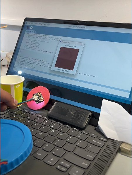
Using the same color sensor setup with the Processing software, we will visualize the detected color on the screen. Just remove all the LEDs.
First, download the Processing software from here.
Install the software, then upload the program given below to your Arduino board.
Note: Make sure the USB cable is connected to the proper port on your laptop while running the software. Also, keep your serial monitor/plotter off.
Arduino program
#include <Wire.h>
#include "Adafruit_TCS34725.h"

// Pins for RGB LED
#define redpin 3
#define greenpin 5
#define bluepin 6
#define commonAnode true

byte gammatable[256];
Adafruit_TCS34725 tcs = Adafruit_TCS34725(TCS34725_INTEGRATIONTIME_50MS, TCS34725_GAIN_4X);

void setup() {
  Serial.begin(9600);

  if (!tcs.begin()) {
    Serial.println("No TCS34725 found ... check your connections");
    while (1)
      ;
  }

  // Gamma correction table
  for (int i = 0; i < 256; i++) {
    float x = i / 255.0;
    x = pow(x, 2.5);
    x *= 255.0;
    gammatable[i] = commonAnode ? 255 - x : x;
  }
}

void loop() {
  uint16_t r, g, b, c;
  tcs.getRawData(&r, &g, &b, &c);

  // Normalize RGB values using clear channel (luminance)
  float red = r / (float)c * 255.0;
  float green = g / (float)c * 255.0;
  float blue = b / (float)c * 255.0;

  // Ensure values stay in bounds
  red = constrain(red, 0, 255);
  green = constrain(green, 0, 255);
  blue = constrain(blue, 0, 255);

  Serial.print("R:\t");
  Serial.print((int)red);
  Serial.print("\tG:\t");
  Serial.print((int)green);
  Serial.print("\tB:\t");
  Serial.print((int)blue);
  Serial.print("\tC:\t");
  Serial.println(c);

  delay(100);
}
Next, paste this code inside this new software window and click on ‘Run’.
Processing code
import processing.serial.*;

Serial myPort;  // Serial port for communication
float red = 0, green = 0, blue = 0, clear = 0;  // RGB and clear values from Arduino

void setup() {
  size(400, 400);  // Window size
  String portName = Serial.list()[0];  // Automatically select the first available port
  myPort = new Serial(this, portName, 9600);  // Open serial port
  myPort.clear();  // Clear old data in the buffer
  myPort.bufferUntil('\n');  // Wait for a full line of data
}

void draw() {
  background(255);  // White background

  // Detect color name and adjust displayed color
  String detectedColor = detectColor(red, green, blue, clear);

  if (detectedColor.equals("No Color Detected")) {
    // Draw a red "X" for No Color Detected
    fill(255, 0, 0);  // Red color
    stroke(255, 0, 0);
    strokeWeight(8);
    line(100, 100, 300, 300);  // Diagonal line 1
    line(100, 300, 300, 100);  // Diagonal line 2
    noStroke();
  } else {
    // Set fill color based on detected color
    if (detectedColor.equals("Black")) {
      fill(0);  // Black
    } else if (detectedColor.equals("White")) {
      fill(255);  // White
    } else {
      fill(red, green, blue);  // Use detected RGB values for other colors
    }

    noStroke();
    rect(50, 50, width - 100, height - 100);  // Draw rectangle
  }

  // Display detected color name and values
  fill(0);  // Black text
  textSize(20);
  textAlign(CENTER);
  text("Detected Color: " + detectedColor, width / 2, 30);
  text("R: " + int(red) + " G: " + int(green) + " B: " + int(blue) + " C: " + int(clear), width / 2, height - 20);
}

void serialEvent(Serial myPort) {
  String data = myPort.readStringUntil('\n');  // Read Serial data
  if (data != null) {
    data = trim(data);  // Remove whitespace
    String[] values = split(data, '\t');  // Split by tab characters
    if (values.length >= 8) {  // Ensure we have R, G, B, C values
      try {
        // Parse and update RGB and clear values
        red = float(values[1]);
        green = float(values[3]);
        blue = float(values[5]);
        clear = float(values[7]);
      } catch (Exception e) {
        println("Error parsing values: " + e.getMessage());
      }
    }
  }
}

String detectColor(float r, float g, float b, float c) {
  if (c < 400) return "Black";  // Low clear value indicates black
  if (c > 1600 && abs(r - g) < 50 && abs(g - b) < 50) return "White";  // High clear, similar RGB values
  if (c > 600 && c < 1200 && abs(r - g) < 30 && abs(g - b) < 30) return "No Color Detected";  // Mid-range clear, no distinct color
  if (r > g && r > b) return "Red";
  if (g > r && g > b) return "Green";
  if (b > r && b > g) return "Blue";
  return "Unknown";
}