Hi, are you a college student and need help with an electronics project? Worry not! as we have many good electronics projects in our arsenal. From beginner-level projects covering 2-3 sensors or modules with Arduino to advanced-level projects covering machine learning and AI projects using Raspberry Pi, we got you covered.
We can help you to excel in your college project seminar or exhibition in three ways:
Electronics project list
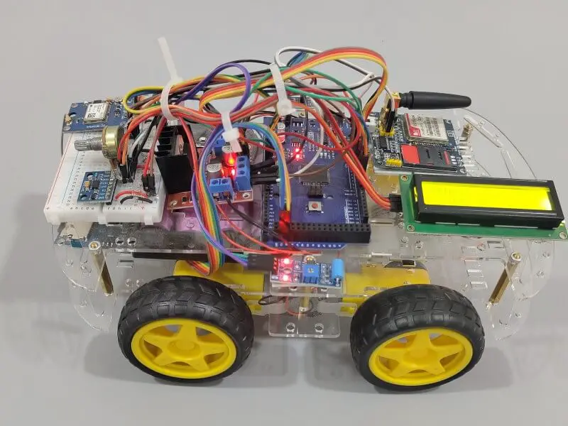
1) Accident detection and live location project
Features
- Real-time accident detection and alert system.
- Data logging capability for storing sensor readings.
- LCD display for user interface.
- Arduino Mega microcontroller for backend processing.
- Multiple sensors including Adafruit ADXL345 Accelerometer, DS18B20 Temperature Sensor, and Vibration Sensor.
- SIM900A GSM Module for SMS alerts in case of accidents.
- SD Card Module for storing logged data.
Working
- The Adafruit ADXL345 Accelerometer continuously monitors the vehicle’s acceleration.
- The DS18B20 Temperature Sensor measures the temperature inside the vehicle.
- The Vibration Sensor detects sudden impacts or collisions.
- The Arduino Mega processes data from these sensors in real-time.
- If a significant acceleration change or vibration indicative of an accident is detected, the Arduino triggers an alert.
- The alert can be displayed on the LCD display for the user to see.
- Additionally, the Arduino sends an SMS alert using the SIM900A GSM Module to predefined contacts.
- The Arduino also logs sensor data to an SD card for later analysis and investigation.
Components
- Arduino Mega.
- Adafruit ADXL345 accelerometer.
- DS18B20 temperature sensor.
- Vibration sensor.
- LCD display.
- SIM900A GSM module.
- SD Card module.
- Power source (e.g., battery pack or vehicle power supply).
- Breadboard and jumper wires for circuit connections.
- Car chassis
2) Earthquake detector

Features
- Real-time earthquake detection using the ADXL345 accelerometer sensor.
- Threshold-based seismic activity detection triggers an alert through a buzzer.
- Optional LCD for visual notification of earthquake alerts.
- Data transmission to a computer for graph plotting and visualization.
- Seismic graph plotting in Python using Matplotlib for real-time monitoring.
- Modular design allows for further enhancements and integration with
additional sensors.
Working
- The ADXL345 accelerometer continuously measures acceleration along the X, Y, and Z axes.
- Arduino processes accelerometer data and compares it against a predefined threshold to detect seismic activity.
- If seismic activity exceeds the threshold, Arduino triggers a buzzer alert.
- Optionally, Arduino can display earthquake alerts on an LCD screen.
- Simultaneously, Arduino transmits seismic data to a computer via serial communication.
- A Python script running on the computer receives the data, processes it, and plots it on a graph using Matplotlib.
- Users can monitor real-time seismic activity through the graphical interface.
Components
- Arduino Uno or similar microcontroller.
- Motor driver module (e.g., L298N) to control the motors.
- DC motors for propulsion.
- IR receiver module to receive signals from the remote control.
- IR remote control.
- Wheels and chassis for the car.
- Power source (e.g., battery pack or power supply).
- Ultrasonic sensors (optional) for obstacle detection.
- LED indicators.
- Breadboard and jumper wires for circuit connections.
3) Path memorizing robot

Features
- A wireless IR remote control car using Arduino plus
- Turn it into a path-memorizing robot using the same setup
- Can remember the path even if the power is cut.
- Tinkercad simulation file with real-time simulation
Working
- The robot is controlled via an IR remote.
- The IR receiver connected to the robot receives the wireless data from the remote and performs the corresponding task.
- For example, when button 2 is pressed on the remote, the receiver decodes the signal and gives the data to the Arduino.
- The Arduino then gives the command to both motors to rotate forward, thus moving the forward.
- The car automatically stores the path once it starts running. The same path is repeated when the assigned ‘path repeat’ button is pressed
Components
- One Arduino Uno
- An IR Remote and IR receiver
- Two geared DC Motors
- Motor driver module
- 9V Power supply.
- Robot wheels
- Robot chassis
- Breadboard
- Wires
4) IR remote control car

Features
- Wireless control of a car using an infrared (IR) remote.
- Forward, backward, left, and right movement capabilities.
- Adjustable speed control for smooth maneuverability.
- Obstacle detection and avoidance system for enhanced safety.
- LED indicators for status feedback.
- Simple and intuitive operation suitable for beginners.
Working
- The Arduino receives signals from an IR remote control.
- Based on the received signals, the Arduino controls the direction and speed of the car’s motors.
- Forward and backward movement is achieved by controlling the rotation of the motors in opposite directions.
- Left and right turns are accomplished by adjusting the rotation of the motors asymmetrically.
- An obstacle detection system, such as ultrasonic sensors, can be integrated to detect obstacles and adjust the car’s movement accordingly.
- LED indicators provide feedback on the current status, such as power on/off, direction of movement, and obstacle detection.
Components
- Arduino Uno or similar microcontroller.
- Motor driver module (e.g., L298N) to control the motors.
- DC motors for propulsion.
- IR receiver module to receive signals from the remote control.
- IR remote control.
- Wheels and chassis for the car.
- Power source (e.g., battery pack or power supply).
- Ultrasonic sensors (optional) for obstacle detection.
- LED indicators.
- Breadboard and jumper wires for circuit connections.
5) Step counter using Arduino

Features
- Accurate step counting using the ADXL345 accelerometer sensor.
- Real-time display of step count on an OLED or LCD screen.
- Adjustable sensitivity for detecting different walking speeds.
- Reset functionality to clear the step count.
- Low-power consumption, suitable for portable applications.
- Compact design for easy integration into wearable devices.
Working
- The ADXL345 accelerometer sensor measures acceleration along the X, Y, and Z axis.
- Arduino/ESP32 processes the accelerometer data to detect footsteps based on predefined thresholds and patterns.
- Each detected footstep increments the step counter.
- The OLED or LCD display shows the current step count in real-time.
- Users can reset the step counter to zero using a button or through a menu option.
- The system operates efficiently
Components
- Arduino Uno or ESP32 microcontroller.
- ADXL345 accelerometer sensor.
- OLED display or LCD 16×2 screen.
- Push button for resetting the step counter (optional).
- Resistors, capacitors, and jumper wires for circuit connections.
- Breadboard for prototyping.
- Power source (e.g., battery pack or power supply).
6) Maths Quiz game

Features
- Cool maths quiz game
- LCD will display the maths questions one by one. You have to answer each answer within the time frame.
- You will get one point for each successful answer.
- Buzzer produces different sounds in different scenarios.
- Displays the high score.
Components
- Arduino UNO
- Keypad
- LCD(16×2)
- Buzzer
- 10K potentiometer
- Breadboard
- Jumper wires
7) Dc motor control using LDR

Features
- With the increase in light intensity, the speed of the DC motor increases and vice versa.
- A simple breadboard version is available.
- An external supply is needed for high-current motors.
Components
- Arduino UNO
- TIP122 transistor
- Potentiometer
- Buzzer
- 1N4007 diode
- 1K ohm resistor
- LDR
- 9V supply
8) Temp. controlled fan

Features
- With the increase in temperature, the speed of the fan increases and vice versa.
- The temperature and speed of the fan are displayed on the serial monitor.
- Up to two fans can be controlled.
Components
- Arduino UNO
- L293D motor driver
- LM35 temperature sensor
- Simple DC motor/ Axial fan
- Breadboard
- Jumper wires
9) Music reactive LED strip

Features
- The LEDs respond to the music. The louder the music, the better the effect.
- Place the LED strip around your bench and enjoy the show.
Components
- Arduino UNO
- Sound sensor
- 1K ohm resistor
- LED strip
- BC547 transistor
- Breadboard
10) 5 Sensors with 1 Arduino

Features
- 5 sensors display 5 different data on the LCD.
- Each sensor has a designated LED as an output.
- For example, when the PIR sensor detects something, the first LED turns on.
- The ultrasonic sensor measures the distance between it and the object in front. This is a small ‘distance measurement’ project in itself.
- Similarly, the DHT11 sensor gives the humidity and temperature readings on the display.
Components
- Arduino UNO
- PIR sensor
- IR sensor
- DHT11
- HC-SR04
- LDR
- 220 ohm resistor x 6
- LED x 5
- LCD(16×2)
- Breadboard
- Buzzer
11) Line follower

Features
- Autonomous navigation of a robot along a black line using two IR sensors.
- Basic control algorithm for adjusting motor speed and direction based on
sensor readings. - LED indicators for status feedback.
- Easy-to-understand implementation suitable for beginners.
Working
- The Arduino receives input from two IR sensors mounted underneath the robot.
- The IR sensors detect the contrast between the black line and the surrounding surface.
- If both sensors detect the line, the robot continues moving forward.
- If one sensor detects the line while the other does not, the robot adjusts its direction to follow the line.
- LED indicators provide feedback on the robot’s status, such as power on/off and line detection.
Components
- Arduino Uno or similar microcontroller.
- Two IR sensor modules for line detection.
- DC motors and motor driver module (e.g., L298N) for propulsion.
- Wheels and chassis for the robot.
- Battery pack or power supply for powering the motors and Arduino.
- LED indicators (optional) for visual feedback.
- Breadboard and jumper wires for circuit connections.
12) Never falling Robo

Features
- Autonomous operation for edge detection and avoidance.
- Utilizes sensors to detect edges and obstacles.
- Actuators provide corrective actions to avoid falling off edges.
- Customizable parameters for different terrains and environments.
- Compact and lightweight design for maneuverability.
Working
- The robot is equipped with sensors to detect edges, such as infrared (IR) sensors or ultrasonic sensors.
- Arduino microcontroller processes data from the sensors to determine the robot’s proximity to edges or obstacles.
- When an edge or obstacle is detected, the Arduino triggers corrective actions using actuators (e.g., motors or servos) to adjust the robot’s direction and avoid falling off edges.
- The robot continuously scans its surroundings and adjusts its movements accordingly to avoid edges and obstacles.
Components
- Arduino microcontroller (e.g., Arduino Uno).
- Infrared (IR) sensors or ultrasonic sensors for edge detection.
- Motors or servos for actuation.
- Wheels or other locomotion mechanisms.
- Power source (e.g., battery pack).
- Chassis and structural components for building the robot.
13) IoT based fuel indicator

Features
- Real-time monitoring of fuel levels using an ultrasonic sensor.
- Display of fuel levels on an OLED/LCD screen.
- Integration with an ESP32 for IoT capabilities, including data transmission to a
web application for remote monitoring. - Web application interface for viewing fuel levels remotely.
- Low-power operation for extended battery life.
- Customizable alert system for low fuel levels.
Working
- The ultrasonic sensor measures the distance to the surface of the fuel in the tank.
- The ESP32 microcontroller processes the sensor data and calculates the corresponding fuel level.
- The fuel level data is displayed on an OLED/LCD screen for local monitoring.
- The ESP32 establishes a connection to a Wi-Fi network and transmits the fuel level data to a web application.
- Users can access the web application to remotely monitor the fuel levels in real-time.
- An alert system can be implemented to notify users when the fuel level drops below a certain threshold, either locally on the display or through the web application.
Components
- ESP32 microcontroller.
- Ultrasonic sensor (e.g., HC-SR04) for fuel level measurement.
- OLED or LCD display for local monitoring.
- Wi-Fi module integrated into the ESP32.
- Power source (e.g., battery pack or power supply).
- Breadboard and jumper wires for circuit connections.
- Computer with internet access for hosting the web application.
14) IoT parking system

Features
- Real-time monitoring of parking space occupancy using IR sensors.
- Integration with an ESP32 for IoT capabilities, including data transmission to a
web application for remote monitoring. - Display of parking space availability on an OLED screen.
- Web application interface for viewing parking space availability remotely.
- Low-power operation for extended battery life.
- Customizable alert system for full parking spaces.
Working
- IR sensors are placed at each parking space to detect the presence of vehicles.
- The ESP32 microcontroller processes the sensor data and determines the occupancy status of each parking space.
- Occupancy data is transmitted to a web application via Wi-Fi for remote monitoring.
- The ESP32 also displays parking space availability on an OLED screen for local monitoring.
- Users can access the web application to view parking space availability in real-time.
- An alert system can be implemented to notify users when parking spaces are full.
Components
- ESP32 microcontroller.
- IR sensors (e.g., IR reflective sensors or IR proximity sensors) for detecting vehicle presence.
- Wi-Fi module integrated into the ESP32.
- OLED display for local monitoring.
- Power source (e.g., battery pack or power supply).
- Breadboard and jumper wires for circuit connections.
- Computer with internet access for hosting the web application.
15) Weighing scale using arduino

Features
- Accurate weight measurement using a load cell and HX711 amplifier.
- Display of weight readings on an LCD or OLED screen.
- Compact and portable design suitable for various applications.
- Calibration functionality for accurate measurements.
- Low-power operation for extended battery life.
- Customizable units of measurement (e.g., grams, kilograms, pounds).
Working
- The load cell measures the weight placed on the weighing scale platform.
- The HX711 amplifier converts the load cell’s analog output into a digital signal.
- The Arduino reads the digital signal from the HX711 and calculates the weight based on calibration parameters.
- The weight reading is displayed on an LCD or OLED screen for user visualization.
- Users can calibrate the weighing scale to ensure accurate measurements using known weights.
- The system operates efficiently to conserve power, making it suitable for battery-powered applications.
Components
- Arduino Uno or similar microcontroller.
- HX711 amplifier module for load cell interfacing.
- Load cell suitable for the desired weight range.
- LCD or OLED display for displaying weight readings.
- Potentiometer for adjusting contrast (if using an LCD).
- Power source (e.g., battery pack or power supply).
- Breadboard and jumper wires for circuit connections.
- Mechanical Load Cell Setup
16) Heart rate monitor

Features
- Accurate weight measurement using a load cell and HX711 amplifier.
- Display of weight readings on an LCD or OLED screen.
- Compact and portable design suitable for various applications.
- Calibration functionality for accurate measurements.
- Low-power operation for extended battery life.
- Customizable units of measurement (e.g., grams, kilograms, pounds).
Working
- The load cell measures the weight placed on the weighing scale platform.
- The HX711 amplifier converts the load cell’s analog output into a digital signal.
- The Arduino reads the digital signal from the HX711 and calculates the weight based on calibration parameters.
- The weight reading is displayed on an LCD or OLED screen for user visualization.
- Users can calibrate the weighing scale to ensure accurate measurements using known weights.
- The system operates efficiently to conserve power, making it suitable for battery-powered applications.
Components
- Arduino Uno or similar microcontroller.
- HX711 amplifier module for load cell interfacing.
- Load cell suitable for the desired weight range.
- LCD or OLED display for displaying weight readings.
- Potentiometer for adjusting contrast (if using an LCD).
- Power source (e.g., battery pack or power supply).
- Breadboard and jumper wires for circuit connections.
- Mechanical Load Cell Setup
17) Garbage level detector

Features
- Real-time monitoring of garbage level using an ultrasonic sensor.
- Integration with an ESP32 for data processing and communication.
- Local web application for remote monitoring of garbage level.
- Customizable threshold alerts for garbage level management.
- Low-power operation for extended battery life.
- User-friendly interface for easy monitoring and management.
Working
- The ultrasonic sensor measures the distance to the surface of the garbage.
- The ESP32 microcontroller processes the sensor data and calculates the garbage level.
- Garbage level data is transmitted to a local web server hosted on the ESP32.
- Users can access the web application on their computer or mobile device connected to the same network to monitor garbage level in real-time.
- Threshold alerts can be implemented to notify users when the garbage level reaches predefined limits, indicating the need for emptying or management.
- The system operates efficiently to conserve power, making it suitable for battery-powered applications.
Components
- ESP32 microcontroller.
- Ultrasonic sensor (e.g., HC-SR04) for garbage level measurement.
- Power source (e.g., battery pack or power supply).
- Breadboard and jumper wires for circuit connections.
- Computer or mobile device for accessing the local web application.
18) Traffic sign detector car using RPi

Features
- Combined ambulance alert and traffic sign detection system.
- ESP32-based ambulance detection with buzzer alert.
- Raspberry Pi-based traffic sign detection with automatic speed control.
- Local web app interface for remote control and monitoring.
- Button-triggered ambulance detection on the web app.
- Speed lock mechanism for adherence to speed limits.
- Portable operation using Li-ion batteries and a power bank.
Working
- ESP32 hosts a local web server for ambulance detection.
- A button press on the web app triggers ambulance detection, sending a request to the ESP32.
- Upon detecting an ambulance signal, ESP32 triggers a buzzer alert.
- Raspberry Pi hosts a local web server for traffic sign detection and speed control.
- The web app sends commands to Raspberry Pi for speed control based on detected speed limit signs.
- Raspberry Pi adjusts motor speeds using PWM signals.
- The system ensures adherence to detected speed limits with a speed lock mechanism.
Components
- ESP32 microcontroller for ambulance detection.
- Sensors for ambulance signal detection.
- Buzzer for audible alerts.
- Raspberry Pi with camera module for traffic sign detection.
- Motors and motor drivers for car propulsion.
- Speed sensors for speed measurement.
- Li-ion batteries for portable operation.
- Power bank for additional power supply.
- Custom chassis for the car.