Last updated on April 5th, 2024 at 05:24 pm
A capacitor is an electronic device that can store energy in the form of an electric field and releases it into a circuit wherever possible. Capacitors are used in many electrical and electronic systems for electronic noise filtering, power conditioning, remote sensing, signal coupling or decoupling, and more. This blog post will discuss its symbol, equation, and uses.
What is the difference between capacitor and capacitance?

It is a two-terminal device that stores charge. Its ability to store charges is known as capacitance. They are also known as condensers.
They are rated by their maximum voltage. Hence don’t exceed the applied voltage more than its rated voltage, or it will explode.

Note: They do not generate energy, but can store it or dissipate it. Hence capacitor is a type of passive device.
Table of Contents

Given above is a simple rectifier circuit. A rectifier circuit converts the AC voltage to stable DC voltage with the help of diodes and filters. Diodes used in this circuit convert the input AC waveform into fluctuating DC waveform. This fluctuating DC waveform is then made stable using the electrolytic capacitor as a filter.
Symbol
The symbol contains two parallel lines with a gap between them. i.e., Flat, curved, or an arrow passes through it.
- The flat line denotes that the capacitor is non-polarized.
- The curved line denotes that the capacitor is polarized.
- The arrow type denotes that it is of a variable type.
Schematic symbols are given below:
Polarized capacitor

These are called polarized because they use electrolytes as one of their electrodes. They have positive and negative terminals. Example: Electrolytic capacitor

Note: Don’t wire a polarized capacitor backward, as this can damage the capacitor and the circuit.
Non – polarized / fixed capacitor

These have fixed capacitance values. It can be connected in either direction. Example: Ceramic capacitor
Variable capacitor

These can change their capacitance values. They are used in the tuning circuits to adjust the frequency. The capacitance is varied by increasing or decreasing the effective area between the pairs of conductors that affects the capacitance of the capacitor.
Variable non-polarized / Trimmer capacitor

These are used to calibrate a circuit during manufacturing or troubleshooting. The capacitance is changed using trimming of the dielectric medium.
In both polarized and non-polarized cases, there are two terminals running perpendicularly into pairs of conductors.
What is the unit of capacitance?
The capacitance is measured in Farads and is denoted by (F).
1F = 1 coulomb per volt
A capacitor has the capacitance of one Farad when one coulomb of electric charge is stored in the conductor on applying a voltage of one volt. It is always positive.
Construction

The physical construction of the capacitor varies. It contains two electrical conductors (metal plates) that are separated by a distance. Positive charges (in the form of protons) get deposited on one conductor and negative charges (in the form of electrons) get deposited on the other conductor.

The distance between the conductors is filled by air or vacuum or by some form of a good insulating material such as waxed paper, ceramic, mica, plastic, or some form of liquid gel. This insulating material is known as di-electric.
What is the role of dielectric in a capacitor?
The purpose of a dielectric is to increase the capacitance of the capacitor by reducing the amount of energy that is lost when the electric field is created. The dielectric also helps to protect the plates from being damaged by the electric field. Different types of capacitors are fabricated in many forms, styles, lengths, girths, and materials. They have different dielectric materials present in between the conductors.
Conductors allow an easy path for the electrons to pass through them when it is excited by any power supply but dielectric material present in between them blocks the path of the flow of electrons.
What is a dielectric constant?
The dielectric constant is a measure of the ability of the dielectric to store electrical energy. The higher the dielectric constant, the greater the amount of energy that can be stored in the capacitor. It is a dimensionless quantity relative to free space. A dielectric material with a high dielectric constant is a good insulator.
The term permittivity defines how well dielectric material stores an electric field. Permittivity between the conductors is equal to the product of permittivity of free space (∈o) and the relative permittivity(∈r) of the material being used as the dielectric. It is given by:
∈ = ∈o x ∈r
How to calculate the capacitance of a capacitor?
The capacitance can be calculated with the help of a formula:
C = εA/d
Where:
- C is capacitance;
- ε is permittivity, a term for how well dielectric material stores an electric field;
- A is the parallel conductor area
- d is the distance between the two conductors.
Let us assume a capacitor with two electrical conductors having charges Q1 and Q2 (Normally if one plate has +q the other has –q charge). The electric field (to store charges) present in between the gap of two electrical conductors depends on the charge given to the electrical conductors. As it is known that potential difference (V) is directly proportional to the electric field hence we can say,
Charge ∝ potential difference
Q ∝ V
Q = CV
This proportionality constant C is known as the capacitance of the capacitor. It is defined as the ratio of the maximum charge (Q) that can be stored in a capacitor to the applied voltage (V) across its conductors.
C = Q/V
Where:
- C is the capacitance in Farads
- Q is the charge held on the conductors in coulombs
- V is the potential difference across the conductors in volts
Specifications
A capacitor’s most basic rating is its capacitance. Capacitance specifies a capacitor’s charge-holding capability per volt. A capacitor also has some other specifications that are discussed below:
- Working Voltage: This is the maximum voltage at which the capacitor operates without failure during its cycle life.
- Tolerance: It is the extent to which the actual capacitance varies from its nominal value.
- Leakage Current: It is the current that will flow through a dielectric when a capacitor discharges.
- Equivalent Series Resistance (ESR): It is the impedance at high frequencies (including the dielectric resistance)
- Working Temperature: The temperature at which it operates nominally.
- Temperature Coefficient: The maximum change in the capacitance value over a specified temperature range.
How can we increase the capacitance of a capacitor?
The following ways can increase the capacitance:
- By choosing a dielectric as good as an insulator
- By decreasing the distance between the electrical conductors
- By increasing the surface area and the size of conductors
Working
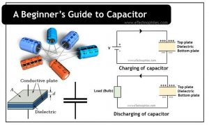
Consider an uncharged capacitor as shown in the figure below. The two plates (conductors) in the capacitors are electrically neutral i.e., they have an equal amount of positive and negative charge.
Charging of capacitor

When a voltage is applied, the electrons (negative charges) in the upper plate get attracted by the positive terminal of the battery. While the negative terminal of the battery pushes the electrons present in the bottom plate of the capacitor.
Now because of the dielectric between the two conductors, electrons collected on the inner side of this capacitor are not able to cross this barrier.
After some time, more electrons will get accumulated at the bottom plate of this capacitor, while the top plate will have a shortage of electrons. (i.e., the top conductor will get positively charged, while the bottom plate will get negatively charged).
And because of these charged particles, a potential difference will develop across the two conductors. This will continue till the point potential difference across the two conductors is equal to the supply voltage.
Hence due to this potential difference, the electric field will develop across the two conductors. And this developed electric field is directly proportional to the potential difference and inversely proportional to the distance between two conductors.
E = V/d
In this way, the energy is stored in the form of an electric field.
Discharging of capacitor

Now even if we remove the voltage source, the plates of this capacitor hold these charges until the terminals are connected in a circuit.
If we connect a bulb as a load across the terminals, the electrons present in the bottom plate will get attracted by the top plate, thus a charge transfer or a current flow takes place through this conductive path and the bulb will glow.
This process will continue till both the plates will become electrically neutral again. When this happens, there will not be any electron flow through the conductive path and the bulb will be turned off. Thus the capacitor is now discharged.
Capacitor in series

When connected in series, the overall capacitance of the circuit is reduced. This is because the capacitors are effectively sharing the voltage across them. The formula for calculating the total capacitance of a series circuit is:
1/Ctotal = 1/C1 + 1/C2 + … + 1/Cn
Capacitors in parallel

When connected in parallel, the overall effect is that of a single capacitor with increased capacitance. The formula for calculating the total capacitance of a parallel circuit is:
Ctotal = C1 + C2 + C3 +… + Cn
Energy of capacitor
The energy is measured in joules and is calculated using the formula:
E = 1/2 CV2
Applications
Some of the applications are listed below:
- For storing energy, which can be used by the device for temporary power outages whenever they need additional power.
- To reduce voltage fluctuations in power supplies and increase the efficiency of power transmission.
- They are used to generate electromagnetic oscillations.
- Used in tuning circuits (with inductors) to select information in a particular frequency band.
- They are also used in electric power distribution for power factor correction.
- It can be used like a temporary battery as it can store energy when connected to a charging circuit and can dissipate that stored energy when disconnected.
FAQs
Is capacitor an active or passive device?
It is a passive device as it can store and release energy but can neither control the flow of current nor inject energy on its own.
Why capacitor blocks DC?
It blocks DC (direct current) due to its ability to store and release electrical energy but not sustain a steady flow of current. It acts like an open circuit for DC after it’s fully charged, preventing further current flow.