
Last updated on November 28th, 2024 at 11:00 am
Have you ever wondered what all those symbols in circuit diagrams mean? They’re the standard drawings we use to represent electrical and electronic components and how they’re connected. Think of them as a universal language that helps engineers, designers, and troubleshooters share technical info easily.
In this guide, we’ll walk you through the essential types of circuit symbols, explaining what they do and how they’re used in both electrical and electronic systems
List of Electrical Symbols
1. Wires and Connections
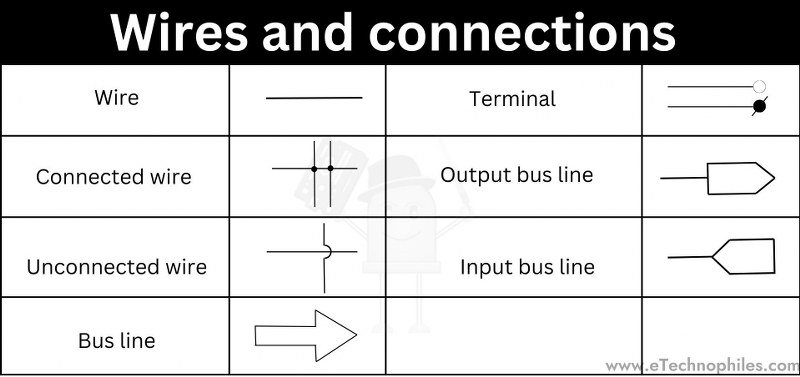
Wires and connections are fundamental elements in any circuit. Their symbols illustrate how different components are connected within the circuit:
- Wire: Simple lines representing electrical connections between components.
- Connected Wires: Indicate junctions where two or more wires are physically connected.
- Unconnected Wires: Represent wires crossing without a connection, typically depicted by a small arc to avoid confusion.
- Input/Output Bus Line: Used in systems with multiple data lines to show bundled signals.
- Terminal: Shows points where wires connect to power supplies, components, or ground.
- Bus Line: Represents multiple wires or signals grouped together for organization.
2. Power Supply
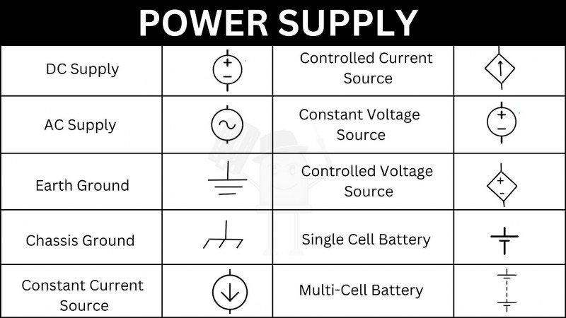
Power supply symbols represent the sources of energy in a circuit. These can be either direct current (DC) or alternating current (AC) sources.
- DC Supply: A symbol representing a direct current source.
- AC Supply: A symbol for alternating current.
- Earth Ground: Represents the reference point in a circuit with zero voltage (ground).
- Chassis Ground: Indicates grounding through the device’s chassis or frame.
- Constant Current Source: Provides a fixed current regardless of load resistance.
- Controlled Current Source: Provides current that can be externally controlled.
- Constant Voltage Source: Maintains a fixed voltage across its terminals.
- Controlled Voltage Source: Voltage can be controlled externally.
- Single Cell Battery: Represents a single battery cell, often used in small, low-power circuits.
- Multi-Cell Battery: Indicates multiple cells connected in series to increase voltage.
3. Diodes
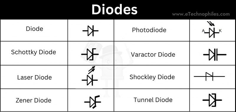
Diodes are semiconductor devices that allow current to flow in one direction. Different types of diodes serve various functions.
- Diode: The basic symbol for a diode, which allows current flow in one direction.
- Schottky Diode: Known for its fast switching and low voltage drop.
- Laser Diode: Emits a focused, coherent light beam, used in optical systems.
- Zener Diode: Allows current to flow in reverse when a specific voltage is exceeded, often used for voltage regulation.
- Photodiode: Converts light into electrical current.
- Varactor Diode: Acts as a variable capacitor when reverse-biased, used in tuning circuits.
- Shockley Diode: A four-layer diode used in switching applications.
- Tunnel Diode: Exhibits negative resistance, used in high-speed switching.
4. Switches
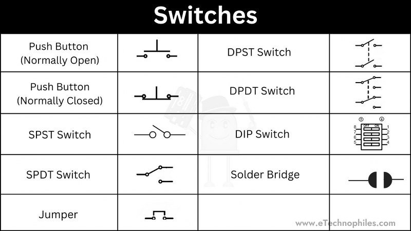
Switches control the flow of electricity by opening or closing circuits.
- Push Button (Normally Open): The circuit is open until the button is pressed.
- Push Button (Normally Closed): The circuit is closed until the button is pressed.
- SPST Switch: A single-pole, single-throw switch that toggles a circuit on or off.
- SPDT Switch: A single-pole, double-throw switch that directs current to one of two possible paths.
- DPST Switch: A double-pole, single-throw switch controlling two circuits simultaneously.
- DPDT Switch: A double-pole, double-throw switch, offering two output paths for two circuits.
- DIP Switch: A set of tiny switches used to set configuration options in circuits.
- Jumper: A small conductor used to close or open a circuit connection.
- Solder Bridge: A connection made by a blob of solder used for permanent circuit modifications.
5. Transistors and FETs
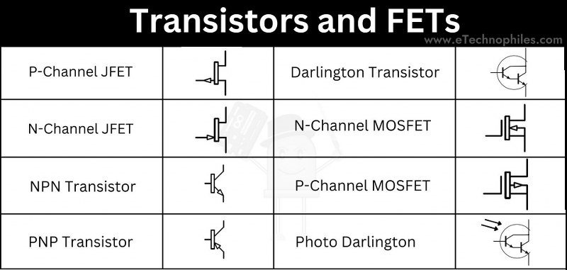
Transistors are critical in amplifying or switching electrical signals. Field-effect transistors (FETs) use voltage to control current flow.
- P-Channel JFET: A type of transistor that controls current with a positive voltage at the gate.
- N-Channel JFET: A transistor controlled by a negative gate-source voltage.
- NPN Transistor: A bipolar junction transistor (BJT) where current flows from the collector to the emitter.
- PNP Transistor: Current flows from the emitter to the collector when negative voltage is applied to the base.
- Darlington Transistor: A combination of two BJTs to provide high current gain.
- N-Channel MOSFET: A transistor that is normally off but switches on when voltage is applied to the gate.
- P-Channel MOSFET: A transistor that is normally on but turns off when voltage is applied to the gate.
- Photo Darlington: A transistor that amplifies light-triggered signals, often used in optoelectronic applications.
6. Logic Gates
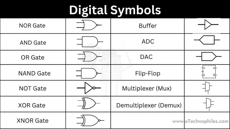
Logic gates are fundamental in digital circuits, used to perform logical operations based on input signals.
- NOR Gate: Outputs true only when all inputs are false.
- AND Gate: Outputs true only when all inputs are true.
- OR Gate: Outputs true when any input is true.
- NAND Gate: Outputs true unless all inputs are true.
- NOT Gate: Inverts the input signal.
- XOR Gate: Outputs true when inputs are different.
- XNOR Gate: Outputs true when inputs are the same.
- Buffer: Strengthens the signal without changing its logic state.
- ADC (Analog to Digital Converter): Converts analog signals to digital data.
- DAC (Digital to Analog Converter): Converts digital data to analog signals.
- Flip-Flop: A bistable device that stores a single bit of data.
- Multiplexer (Mux): Selects one of several input signals and forwards it to a single output.
- Demultiplexer (Demux): Takes a single input and routes it to one of many outputs.
7. Capacitors
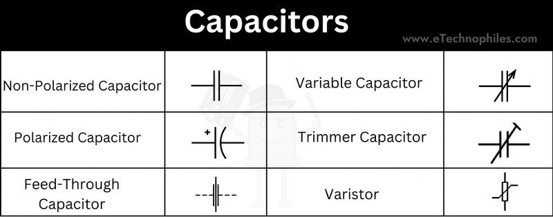
Capacitors store and release electrical energy, and their symbols vary by type.
- Non-Polarized Capacitor: Can be connected in any direction.
- Polarized Capacitor: Must be connected with correct polarity.
- Feed-Through Capacitor: Provides high-frequency filtering.
- Variable Capacitor: Allows manual adjustment of capacitance.
- Trimmer Capacitor: A small adjustable capacitor used for fine-tuning.
- Varistor: A variable resistor that protects circuits from voltage spikes.
8. Resistors
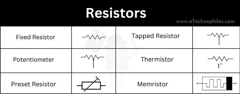
Resistors limit current or divide voltage in circuits.
- Fixed Resistor: Provides a constant resistance value.
- Potentiometer: A variable resistor used for adjusting voltage or current.
- Preset Resistor: A variable resistor set during circuit calibration.
- Tapped Resistor: A resistor with intermediate connections along its length.
- Thermistor: A temperature-sensitive resistor.
- Memristor: A component that “remembers” its resistance based on the charge passed through it.
9. Oscillators and Signal Generators
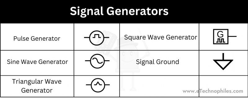
Oscillators and signal generators produce specific waveforms for circuit operations.
- Pulse Generator: Generates pulses at regular intervals.
- Sine Wave Generator: Produces a sine wave signal.
- Triangular Wave Generator: Creates a triangular waveform.
- Square Wave Generator: Produces square wave signals with variable duty cycles.
- Signal Ground: Represents a reference point in a circuit, often at zero volts.
10. Inductors and Transformers
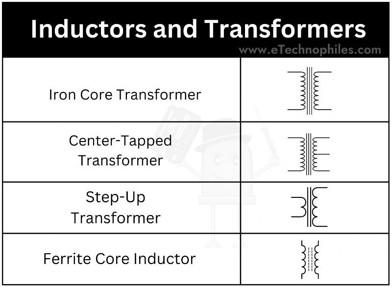
Inductors store energy in magnetic fields, and transformers transfer energy between circuits.
- Iron Core Transformer: A transformer using iron to enhance magnetic coupling.
- Center-Tapped Transformer: A transformer with a tap at the center of the secondary winding.
- Step-Up Transformer: Increases voltage from the primary to the secondary winding.
- Ferrite Core Inductor: Inductors using ferrite cores for high-frequency applications.
11. Sensors and Indicators
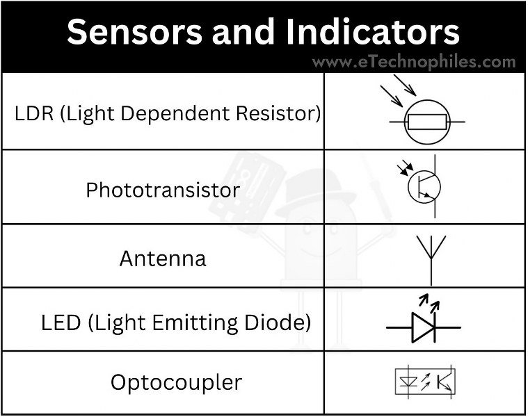
Sensors detect changes in physical conditions and convert them into electrical signals.
- LDR (Light Dependent Resistor): Changes resistance based on light intensity.
- Phototransistor: A transistor controlled by light exposure.
- Antenna: Converts electrical signals to electromagnetic waves and vice versa.
- LED (Light Emitting Diode): Emits light when current flows through it.
- Optocoupler: Transfers electrical signals between isolated circuits using light.
13. Miscellaneous Components
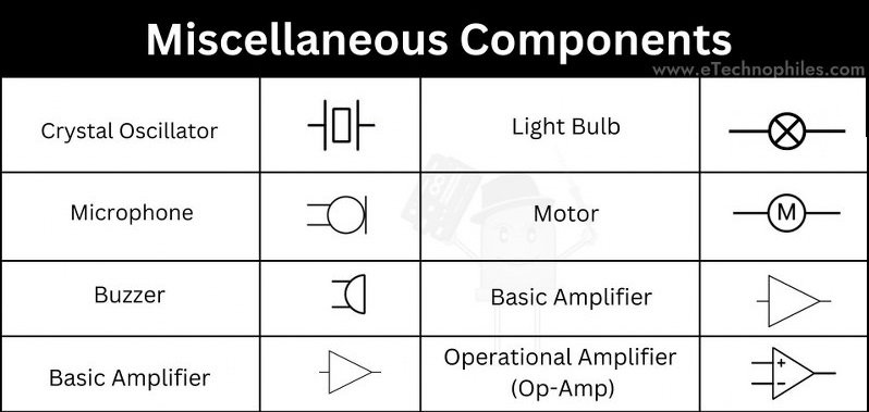
Other symbols that don’t fit neatly into specific categories but are essential:
- Crystal Oscillator: Used for precise frequency control.
- Microphone: Converts sound waves into electrical signals.
- Buzzer: Produces sound when an electrical signal is applied.
- Loudspeaker: Converts electrical signals into sound.
- Light Bulb: Converts electrical energy into light.
- Motor: Converts electrical energy into rotary motion.
- Basic Amplifier: Increases the amplitude of a signal.
- Operational Amplifier (Op-Amp): A highly versatile amplifier used in analog signal processing.
- Buffer: Prevents signal loss by strengthening the signal.