Last updated on March 22nd, 2024 at 12:20 pm
The FTDI interface provides an easy solution to connect the devices with the TTL level interface to USB. As we have already covered the basics of FTDI and how it works in the previous article. We will discuss the FTDI module and cable pinout in this post.
There are two simple devices that convert USB signals to Serial signals (for microcontrollers like Atmega328P): FTDI Cable and Adapter or converter module. Both of them have an onboard FTDI chip. So it is crucial to know and understand their pinout before using them.
Table of Contents
Let’s look at the FTDI adapter Pinout first.
FTDI adapter pinout
The figure below shows the pinout of the FTDI adapter module.

The module has 6 pin headers, which are projected out of the module, and 18 through-hole connectors, which are visible as holes around the module.
The chip is embedded in the middle-left part of the board. The USB space at the left end is the Micro-B USB port to which the USB is connected. The 18 through-hole connectors are also clearly visualized in the pinout.
FTDI adapter specifications
FTDI converter module is used for TTL serial communication. It consists of an FTDI chip integrated with connectors, voltage regulators, Tx/Rx, and other breakout points.
| Specs | Details |
| Chip | FTDI FT232R |
| Pins | 6 pin headers & 18 through-hole connectors |
| Working voltage | 5V DC |
| Output | 3.3 DC – 5 V DC |
| On-board LEDs | Power on, Rx, Tx transmission, working status |
| Pin size | 5 x 2.54 mm |
| Module size | 36 x 18 mm |
| Breadboard friendly | Yes |
| Interfaces | Serial/UART |
| Operating current | 500 mA |
| Ports | Micro-B USB |
The FTDI FT232F chip is the brain of this module. It operates at 3.3V DC or 5V DC. Other important elements integrated into the FTDI module are EEPROM and optional clock generator output. It supports FTDIchip-ID functionality by which a unique identifier is assigned to every chip to provide security.
The module is capable to function at internal clock frequencies ranging from 6MHz, 12MHz, 24MHz, and 48MHz. Thus, it is used to drive microcontrollers. It is connected to the microcontroller through its breakout pins such as Tx, Rx, Vcc, and GND.
The module is connected to the USB port of the other devices using its mini-B USB port. The communication through the interface is performed using TTL to which 500 mA is supplied through the Vcc pin of the module. The device is connected to the breadboard with the 6 header pins.
Now let’s discuss the FTDI Cable pinout.
Here’s the FTDI cable pinout/ color code
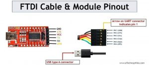
The cable has 6 output pins similar to the FTDI module. The pinout image shows the FTDI to RS232 serial connector. As it is a cable, one end of the cable is the output with the 6 header pins and the other end is the USB connecter. Those 6 pins provide RS232 output which is connected to UART devices with a computer.

The six pins are distinguished using six different colors for easy interpretation. Let’s tabulate the functionality of the 6 pins with their respective colors below:
| Pin Number | Pin Name | Wire Colour | Function |
| 1 | GND | Black | Ground pin |
| 2 | CTS | Brown | Control input used to clear the send request |
| 3 | Vcc | Red | Connection with supply |
| 4 | TxD | Orange | Output data transmission |
| 5 | RxD | Yellow | Input data reception |
| 6 | RTS | Green | Control output to make requests in sending the data |
How to use the FTDI cable with a microcontroller like atmega328p?

Before establishing a successful connection between a PC and a microcontroller, we must connect the pins in the correct order to create a proper interface.
- Connect the TxD pin of the FTDI cable to the RxD pin of the microcontroller.
- Connect the RxD pin of the FTDI cable to the TxD pin of the microcontroller.
- Connect the Vcc pins of both devices.
- Connect the ground pins of both devices.
- Insert the USB end of the FTDI cable into the PC’s USB port to establish a connection.
If done correctly, the FTDI cable enables a perfect interaction between the PC and microcontroller. The circuit diagram shows UART pins of the ATmega328 microcontroller connected to cable output.
FAQs
What is a FTDI cable?
An FTDI cable is a USB to Serial (TTL level) converter, enabling easy connection of TTL interface devices to USB. It allows communication between computers and devices utilizing serial protocols, typically configured at either 5V or 3.3V, depending on the model.
What is the maximum speed of FTDI cable?
FTDI cables support baud rates up to 3 Mbps (megabits per second)