Whether you are just starting out in electronics or building your first project, a handful of integrated circuits (ICs) appear in almost everything — from hobby kits to commercial products. Mastering these components gives you a solid foundation for embedded systems, robotics, automation, and IoT development.
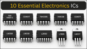
This guide covers 10 essential ICs and digital concepts, explaining what each one does, how it works, and where it is used — without the fluff.
You can also watch the video given below:
1. 555 timer IC
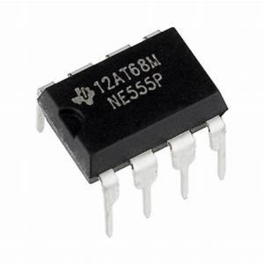
The 555 Timer is one of the most used ICs ever made. Introduced in 1972, it remains popular because it is simple, cheap, and incredibly versatile. With just a few external resistors and capacitors, it generates precise time delays, square waves, and pulse signals.
Three operating modes
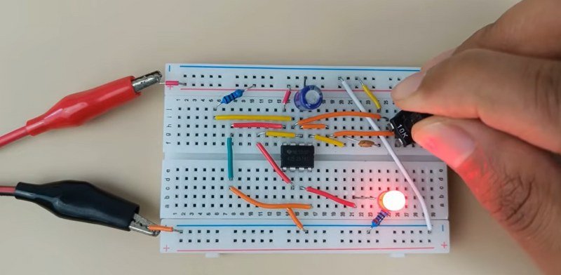
Astable Mode — In this mode the output continuously switches between HIGH and LOW, producing a clock signal. Frequency is set by the timing resistors and capacitor.
For example, in the circuit below, the 555 Timer is configured in astable mode with a potentiometer used as a variable resistor. Adjusting the potentiometer changes the resistance in real time, which directly changes the frequency and duty cycle — and you can see the LED blinking speed vary accordingly.
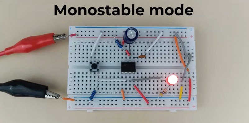
Monostable mode — In this mode, the output produces a single pulse each time it receives a trigger. The output goes HIGH for a fixed duration and then automatically returns LOW on its own.
In monostable circuit, pressing a button causes the output to go HIGH for exactly 1 second and then automatically return LOW on its own — no second press needed. Since the output always returns to one stable state, it is called monostable. Just like before, changing the resistor or capacitor value adjusts the time duration.
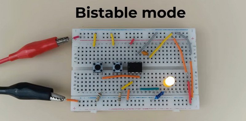
Bistable mode — The output holds its HIGH or LOW state until told to change. Behaves like a basic memory element. Used in toggle switches and electronic latches.
For example, in the circuit below, pressing the SET button turns the LED ON — and it stays ON even after releasing the button. Only when the RESET button is pressed does the LED turn OFF. In a way, it works like a simple memory element storing a single bit of data — similar to a flip-flop.
Common applications
- LED blinkers and flashers
- PWM motor speed controllers
- Audio oscillators and alarm systems
- Sequential and traffic light timers
2. CD4017 decade counter
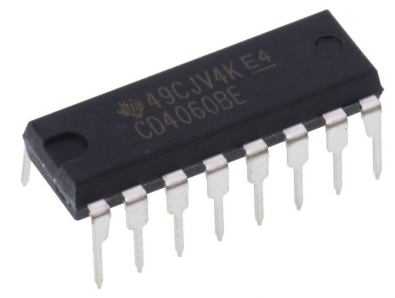
The CD4017 is a decade counter IC that takes a clock signal as input and activates its 10 outputs one at a time in sequence. Every time it receives a pulse, it moves to the next output — like a step-by-step progression.
In the circuit below, the clock input of the CD4017 is connected to the 555 Timer and the outputs are connected to 10 LEDs. As the 555 generates pulses, the LEDs turn ON one after another — creating a running light effect. Once it reaches the last output, it resets and starts again from the beginning, creating a continuous loop.
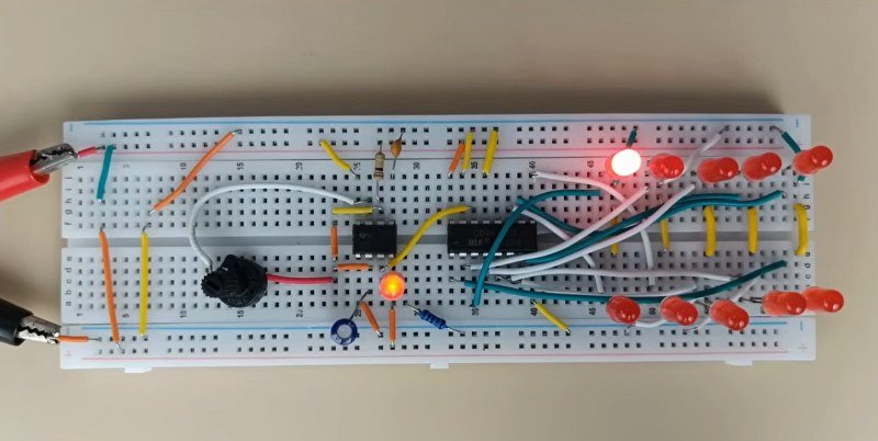
You can also control how many outputs you want to use by resetting the IC early. Instead of cycling through all 10 outputs, simply connect the last required output to the reset pin — and the IC will cycle through only that many LEDs.
Another useful feature is cascading. By chaining two CD4017 ICs together, you can extend the sequence to 20 outputs or even more — and since they all share the same clock signal, the sequence continues smoothly from one IC to the next. No programming or complex setup is needed — just a clock signal and the IC handles all the sequencing.
You can also control the speed of the running pattern simply by adjusting the frequency of the 555 Timer — just change the timing resistor or capacitor values.
Common applications
- LED chaser and running-light effects
- Decorative and sequential lighting
- Basic automation and stepping circuits
3. 74HC595 shift register
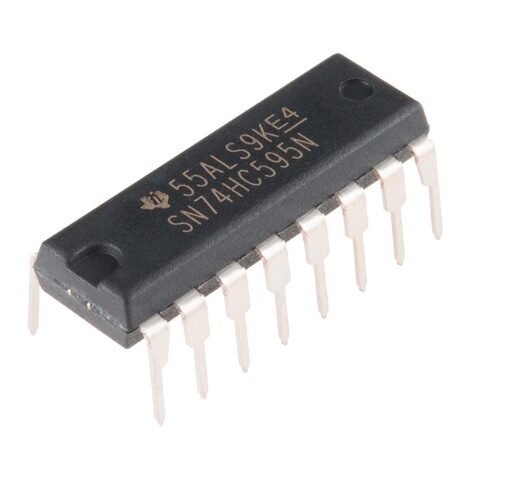
The 74HC595 is a shift register IC that takes data serially — one bit at a time — and converts it into eight parallel outputs. This makes it extremely useful when you need to control many outputs but have limited pins available.
With the CD4017, outputs activate in a fixed sequence based on the clock. With the 74HC595, you have full control — you decide exactly which outputs are ON or OFF by sending your own data.
The IC uses three control pins:
- Data pin — sends one bit at a time into the IC
- Clock pin — each pulse shifts the incoming bit into the next internal position
- Latch pin — once all 8 bits are loaded, a pulse on this pin updates all outputs simultaneously
For example, in the circuit below, an ESP32 sends values from 0 to 255 through the data pin — one bit per clock pulse. After all 8 bits are shifted in, the latch pin triggers and all 8 LEDs update at once, displaying the binary pattern of that value. As the value increments, different LED combinations turn ON and OFF, creating continuously changing animations.
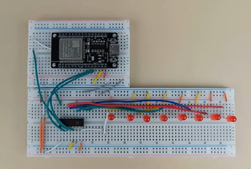
This also saves pins significantly. Normally, controlling 8 LEDs would require 8 separate microcontroller pins. With the 74HC595, you need just 3 — no matter how many ICs you chain.
And chaining is straightforward: connect the serial output of one IC to the data input of the next. Two ICs give you 16 outputs, three give you 24 — all still using the same 3 control pins.
Common applications
- Driving LED matrices and 7-segment displays
- Expanding GPIO on Arduino and ESP32 boards
- Controlling relays, indicators, and custom output panels
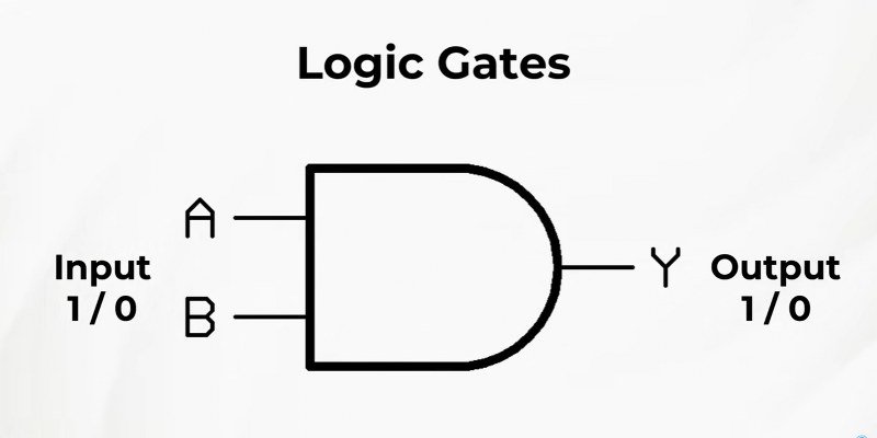
4. Logic Gates
Logic gates are the fundamental building blocks of digital electronics. They take one or more binary inputs — HIGH or LOW — and produce an output based on a fixed logical rule. Instead of turning things ON or OFF manually, logic gates let circuits respond automatically to different input conditions.
Three gates form the essential foundation:
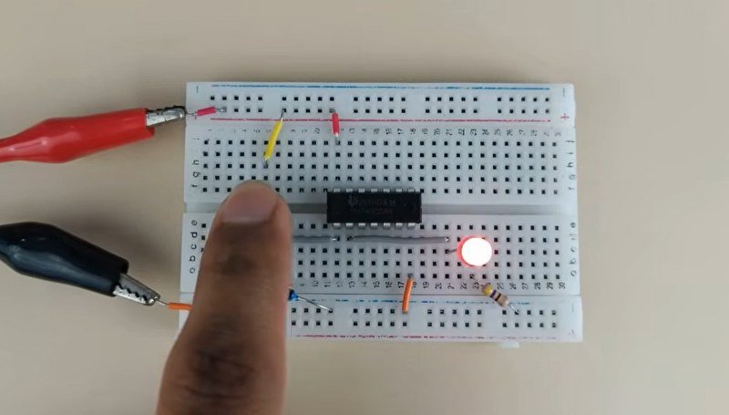
AND Gate (IC: 74HC08) — Output is HIGH only when all inputs are HIGH. Think of it as requiring every condition to be true simultaneously. For example, in a two-input setup, pressing only one button does nothing — both must be pressed for the LED to turn ON.

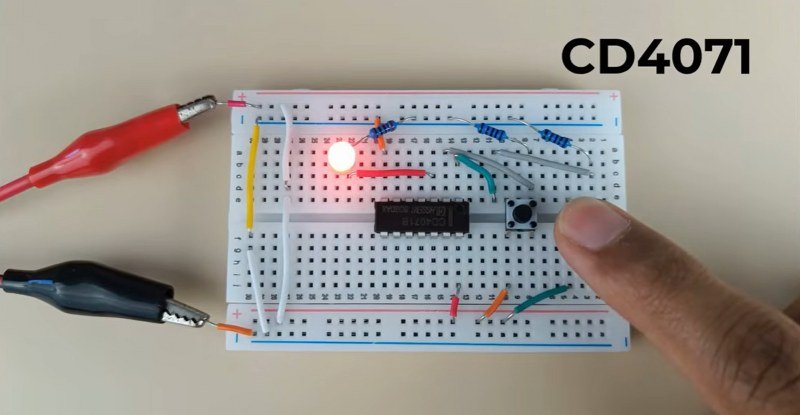
OR Gate (IC: CD4071) — Output is HIGH when at least one input is HIGH. Only one condition needs to be true. With two buttons, pressing either one turns the LED ON.
NOT Gate (Inverter) — Takes a single input and flips it. If the input is HIGH, the output becomes LOW — and vice versa. A simple but essential building block for inverting signals and enabling more complex logic.
By combining these three gates, you can build circuits that make decisions based on any combination of input conditions. And while they may seem abstract, they are working quietly inside every IC covered in this guide — including the 555 Timer and CD4017 — processing signals and controlling how outputs behave.
Common applications
- Safety interlock systems (AND: both conditions must be met)
- Input detection and signal routing
- Building blocks for encoders, decoders, and ALUs
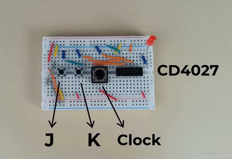
5. JK Flip-Flop CD4027

Logic gates make decisions, but they cannot remember them. As soon as the input changes, the output changes too. A flip-flop solves this — it stores a single bit of data and holds that state until explicitly told to change.
The CD4027 contains two JK flip-flops. It has three key inputs: J, K, and Clock.
Here is the critical detail: the flip-flop only checks J and K when it receives a clock pulse. Not continuously — only on the rising edge of the clock signal.
- When J is HIGH and K is LOW: on the next clock pulse, the output Q goes HIGH and stays HIGH — even after you release J.
- When K is HIGH and J is LOW: on the next clock pulse, Q goes LOW and stays LOW.
- When both J and K are HIGH: the output toggles — it flips to the opposite state on each clock pulse.
For example, in the circuit below, pressing the J button and then the clock button turns the LED ON. Releasing J does nothing — the flip-flop holds the state. Only pressing K and giving another clock pulse turns the LED OFF.
This behaviour makes flip-flops the foundation of digital memory. Registers inside microcontrollers are simply arrays of flip-flops. Counters are flip-flops chained so each one clocks the next. The fundamental concept — store one bit, update only on a clock edge — scales from this single IC all the way up to the memory inside modern processors.
Common applications
- Latching and toggle circuits
- Frequency dividers and binary counters
- Registers and sequential logic inside microcontrollers
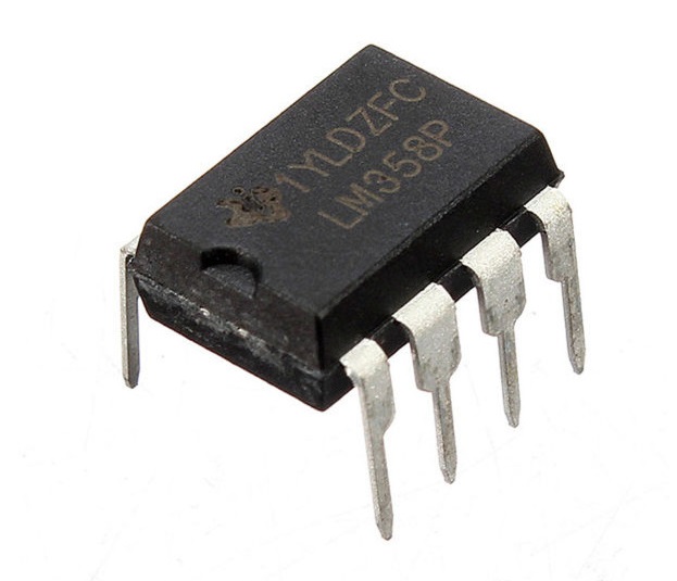
6. Op-Amp LM358
Everything covered so far deals with digital signals — HIGH or LOW, 1 or 0. But the real world is analog. Sensors produce small, continuously varying voltages, not clean binary levels. Before those signals can be processed, they often need amplification — and that is the job of an operational amplifier.
The LM358 contains two op-amps in a single package. Each has two inputs:
- Non-inverting input (+)
- Inverting input (−)
The op-amp amplifies the difference between these two inputs. Even a few millivolts of difference can produce a much larger swing at the output.
Gain is controlled by connecting resistors between the output and the inverting input — a technique called negative feedback. The ratio of these resistors sets exactly how much the signal is amplified. Change the resistor values, change the gain.
For example, in the circuit below, a small input voltage is applied to the non-inverting pin. With feedback resistors setting a gain of, say, 10×, even a tiny change at the input produces a proportionally large change at the output — which you can observe directly on a multimeter or oscilloscope.
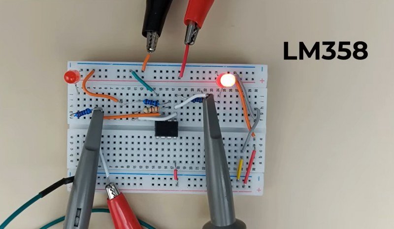
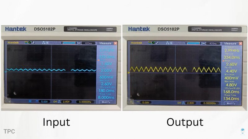
One important constraint: the output can never exceed the supply voltage. If the IC is powered from 5 V, the output is limited to that range. The LM358 handles this gracefully — it works well with a single supply and operates correctly at low voltages, making it well-suited for microcontroller-based projects.
Common applications
- Amplifying signals from temperature, light, and pressure sensors
- Audio preamplifier stages
- Signal conditioning before ADC input on a microcontroller
7. Comparator LM339
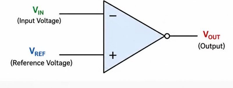
Sometimes you do not need to amplify a signal — you just need to know whether it is above or below a threshold. That is exactly what a comparator does.
The LM339 contains four independent comparators in a single IC. Like an op-amp, each comparator has two inputs. But unlike the LM358, the output is not proportional — it simply switches:
- If the non-inverting input voltage is higher than the inverting input → output goes HIGH
- If it is lower → output goes LOW
In the circuit below, a light-dependent resistor (LDR) is connected in a voltage divider, feeding one input of the comparator. As light intensity changes, the voltage across the LDR changes. A fixed reference voltage — set using a resistor divider or potentiometer — is connected to the other input.
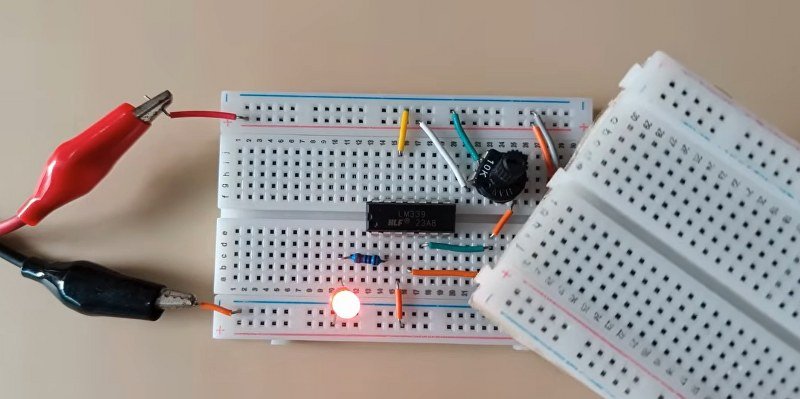
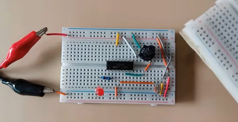
When the light level crosses the reference threshold, the comparator output switches instantly. The LED turns ON in the dark and OFF in the light, or vice versa — depending on how the inputs are wired. And by adjusting the potentiometer, you can set exactly at what light level the switching happens.
This is how many real-world systems work: not reacting to every small fluctuation, but triggering a clear output only when a specific condition is met.
Common applications
- Automatic streetlights and day-night switches
- Battery level monitors and over-voltage detectors
- Sensor threshold detection in alarm systems
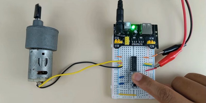
8. L293D motor Driver
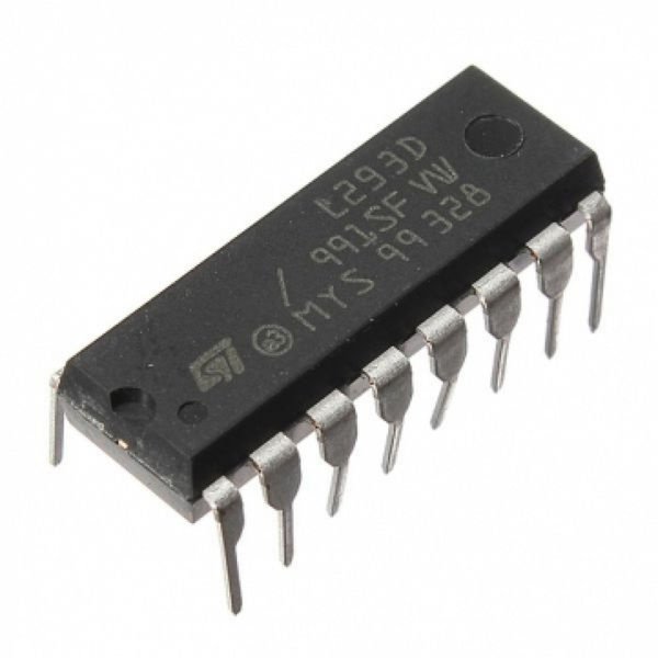
The L293D is a motor driver IC that allows you to control up to two DC motors using low-power control signals.
Motors draw far more current than a microcontroller or logic IC can supply. Attempting to drive a motor directly from a microcontroller pin will damage it. The L293D sits between the two: it accepts low-power control signals on its inputs and drives the motor with a separate, higher-current power supply on its outputs.
Internally it contains an H-bridge circuit, which is the key to controlling motor direction. Depending on the logic applied to the two input pins:
- Input A HIGH, Input B LOW → motor rotates in one direction
- Input A LOW, Input B HIGH → motor rotates in the opposite direction
- Both inputs the same → motor stops
There is also an Enable pin. When HIGH, the motor runs. When LOW, it stops regardless of the input pins — acting as a master on/off switch.
Speed control is where it gets more interesting. Instead of a constant HIGH on the Enable pin, apply a PWM signal — a square wave that switches rapidly between HIGH and LOW. The duty cycle (the proportion of time the signal stays HIGH) controls how much average power reaches the motor. Higher duty cycle means more power and faster rotation; lower duty cycle means slower rotation.
In the circuit below, the PWM output from a 555 Timer is fed into the Enable pin. Adjusting the potentiometer changes the duty cycle in real time, and the motor speed changes accordingly — no microcontroller needed.
Common applications
- DC motor control in robotics and wheeled vehicles
- Fan speed control
- Actuator and conveyor control in automation projects
9. Voltage regulator
Every IC and circuit in this guide depends on one thing above all: a stable supply voltage. Batteries discharge and sag under load. Unregulated wall adapters fluctuate with current draw. Voltage regulators solve this — they take a higher, unstable input voltage and hold the output at a precise, fixed level regardless of load changes.
Linear regulators (e.g. L7805, L7806, L7812)
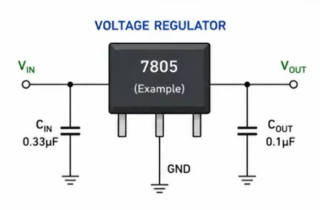
The 78xx series are fixed-output linear regulators. The L7806, for example, always outputs 6 V. Connect an input voltage between roughly 8–35 V, and the output stays at 6 V — stable, clean, and simple to use. Capacitors at the input and output filter out noise and prevent oscillation.
The trade-off: the extra voltage is dissipated as heat. If the input is 12 V and the output is 5 V at 500 mA, the regulator dissipates 3.5 W as heat — and may need a heatsink. Linear regulators are ideal for low-current applications where simplicity and clean output matter more than efficiency.
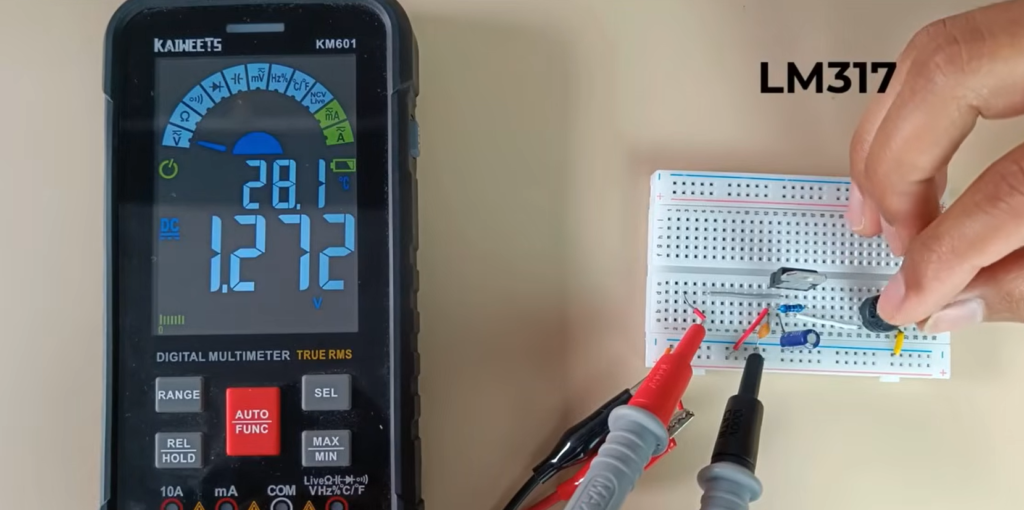
Variable regulators (e.g. LM317)
The LM317 works on the same principle but allows the output voltage to be adjusted using two external resistors or a potentiometer. Instead of a fixed 5 V or 6 V, you can dial in any voltage within the IC’s range — useful when prototyping or when different parts of a circuit need different supply rails.
Switching regulators
Where high efficiency is needed — battery-powered devices, solar systems, high-current loads — switching regulators are the better choice. They convert voltage using rapid switching and inductive energy storage rather than burning off the excess as heat, achieving efficiencies above 90%. They are more complex to design with, but dedicated ICs like the LM2596 make the process manageable.
Common applications
- Multi-rail power supplies in embedded systems
- Providing stable 3.3 V or 5 V rails for microcontrollers and sensors
- Protecting circuits from supply fluctuations