An IR (Infrared) Receiver Sensor is a widely used component in home automation, remote control systems, and robotics. It allows devices to receive infrared signals from an IR remote and convert them into digital signals that can be processed by a microcontroller.
In this tutorial, we will explore how an IR receiver and IR remote work and how to interface it with an Arduino to create a simple home automation project.
Table of Contents
IR Receiver and Remote basics
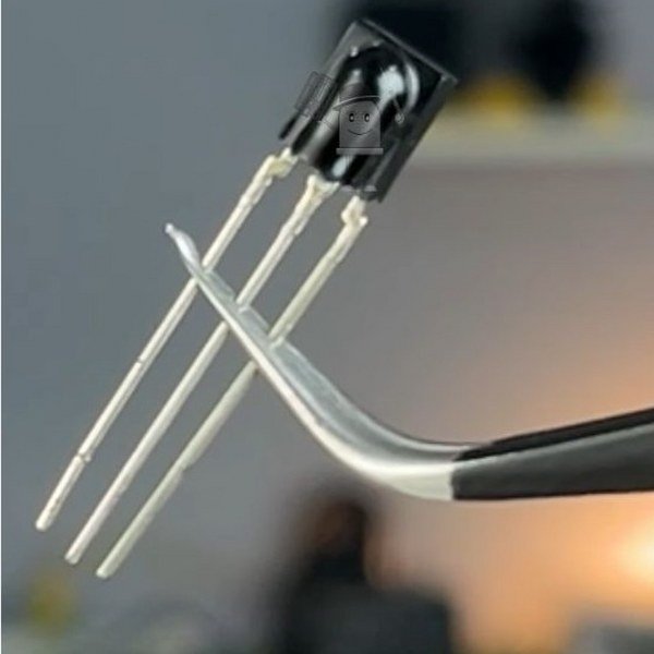
An IR receiver sensor detects infrared signals emitted by an IR remote. It consists of a photodiode and an internal signal processing circuit that decodes modulated IR signals. The IR receiver typically works at a specific frequency (e.g., 38 kHz) and filters out other light sources to prevent false triggers.
It starts with an IR remote:
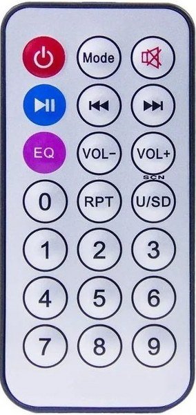
An IR remote control consists of an infrared LED that emits light pulses in a specific pattern. Each button on the remote corresponds to a unique signal, which consists of:
Carrier Frequency: IR remotes typically operate at a frequency of 38 kHz, allowing the signal to be distinguished from ambient IR radiation.
Encoded Data: The button press generates a specific code in a protocol like NEC, Sony, RC5, or Samsung, which is sent as modulated light pulses.
IR receiver:
An IR remote sends pulses of infrared light modulated at a specific frequency (typically 38 kHz). The IR receiver detects these signals, filters out noise, and demodulates them to extract the data. The receiver’s output is then processed by a microcontroller like an Arduino.
It consists of:
- An IR Sensor: Detects incoming infrared pulses.
- A Demodulator Circuit: Extracts the encoded signal from the 38 kHz carrier.
- An Output Pin: Sends the decoded signal to the microcontroller (Arduino).
When the IR receiver receives an IR signal, it outputs a digital waveform representing the encoded data, which the Arduino can process.
How IR Remote and Receiver work together?
- When you press a button on the IR remote, it sends a unique signal.
- The IR receiver module captures and decodes this signal.
- The Arduino/similar controller reads the decoded signal and identifies the button press.
- Based on the received command, the Arduino executes an action (e.g., turning on an LED, controlling a fan, or adjusting brightness).
This simple yet effective communication makes IR technology useful for home automation projects, where an IR remote can control various devices.
IR Receiver Pinout
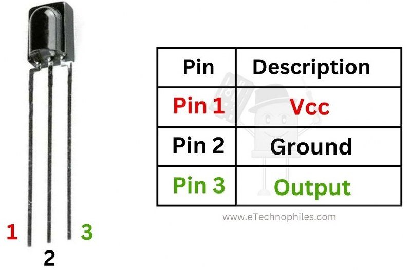
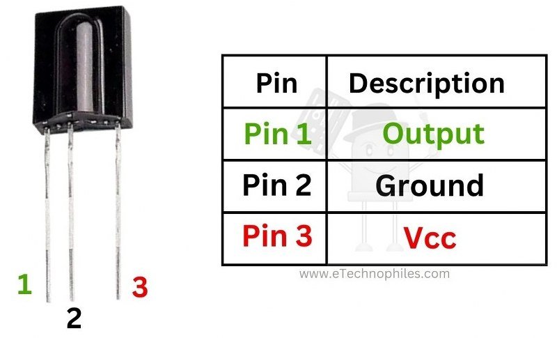
| Pin Number | First Image | Second Image |
|---|---|---|
| Pin 1 | Vcc | Output |
| Pin 2 | Ground | Ground |
| Pin 3 | Output | Vcc |
Specifications
Below is a concise table detailing the typical key specifications of the IR receiver module:
| Parameter | Typical Specification |
|---|---|
| Operating Voltage | 5V DC |
| Current Consumption | ~5mA |
| Carrier Frequency | 38 kHz |
| Output Signal | Digital: LOW when IR signal is detected, HIGH otherwise |
| Detection Range | ~5–10 meters (depends on remote power and obstacles) |
| Viewing Angle | ~45° |
| Response Time | ~50µs |
| Module Dimensions | ~12mm × 5mm |
Note: An IR receiver and an IR remote go hand in hand. No purpose of one without the other.
How to use an IR receiver with Arduino?
Let’s learn how to use an IR receiver with Arduino to read and identify the HEX code of each button on the IR remote. Once the pressed button is identified, we can perform all sorts of tasks such as turning on an LED.
You must have observed a white LED in front of a TV remote. This white LED is an IR transmitter. It transmits Infrared waves of a particular frequency depending on the button pressed.
This wave is then received and decoded by the IR receiver on the TV side, to find out which button you have pressed.
Now to distinguish between the buttons, each button is given a unique frequency. That means you must know what the frequency of each button is before using an IR remote. But the real question is how. Well, an Arduino can help us in this situation. So grab an Arduino and IR receiver.
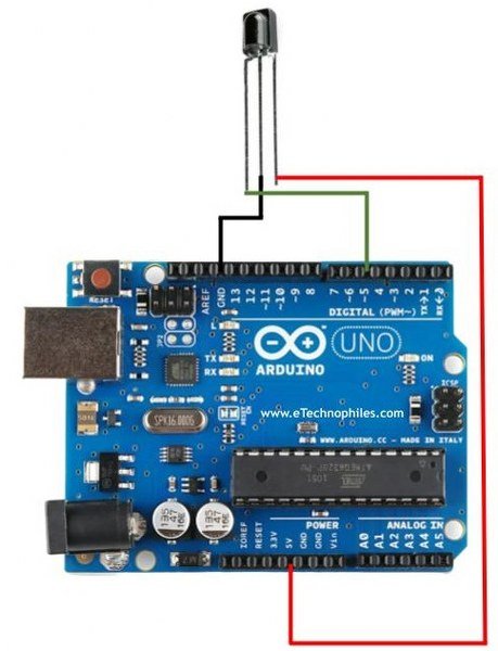
Connect the left terminal of the sensor to digital pin 5 of Arduino. Middle terminal to GND and Right terminal to 5V pin of Arduino.
Now go to Arduino IDE software and download a library: ‘IRremote‘.
Note: Make sure you download the correct version i.e., 2.5 or previous.
Next, go to files, then example–>IR remote–>IRrecieve demo sketch.
#include <IRremote.h>

const int RECV_PIN = 5;
IRrecv irrecv(RECV_PIN);
decode_results results;

void setup(){
  Serial.begin(9600);
  irrecv.enableIRIn();
  irrecv.blink13(true);
}

void loop(){
  if (irrecv.decode(&results)){
        Serial.println(results.value, HEX);
        irrecv.resume();
  }
}
Upload the code to your Arduino board, then open the Serial Monitor. Press any button on the IR remote, and you’ll see its corresponding Hex code displayed. Take note of the Hexadecimal codes for all the buttons. You can now program the Arduino to execute specific functions based on the received Hex codes.
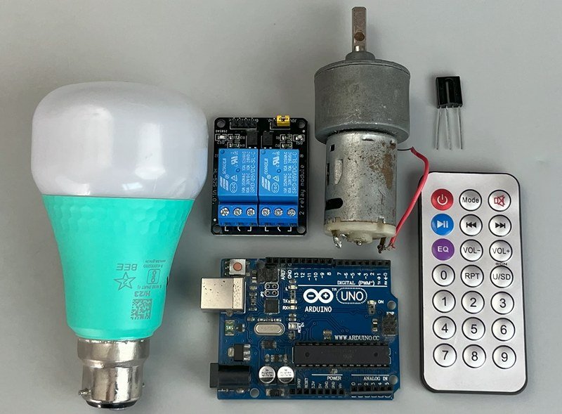
Home automation project using IR Receiver and Remote
Now, let’s build a simple home automation project, using an IR remote to turn on/off an AC light bulb and a DC motor. For this, choose any two buttons of your choice and use the code given before to know their HEX codes.
I am using ‘1’ and ‘2’. Let’s call them Button_1 and Button_2.
Components Required
- Arduino UNO
- IR Receiver
- 2 Channel Relay module
- DC Motor
- Power supply/Battery for motor
- IR remote
- LED Bulb
Circuit Diagram

Program
Upload this program to your Arduino board:
#include <IRremote.h>

#define IR_RECEIVE_PIN 5  // Pin for IR receiver

// Define relay pins
#define RELAY1_PIN 11
#define RELAY2_PIN 12

IRrecv irrecv(IR_RECEIVE_PIN);
decode_results results;

// Define IR remote button codes (replace with actual values from your remote)
#define BUTTON_1 0xFF30CF  // Example hex code for button 1
#define BUTTON_2 0xFF18E7  // Example hex code for button 2

// Relay states
bool relay1State = false;
bool relay2State = false;

void setup() {
  // Initialize Serial Monitor
  Serial.begin(115200);

  // Initialize relay pins as outputs
  pinMode(RELAY1_PIN, OUTPUT);
  pinMode(RELAY2_PIN, OUTPUT);

  // Ensure relays are off initially
  digitalWrite(RELAY1_PIN, HIGH);
  digitalWrite(RELAY2_PIN, HIGH);

  // Initialize IR receiver
  Serial.println("Enabling IRin");
  irrecv.enableIRIn();

  Serial.println("Ready to receive IR signals");
}

void loop() {
  if (irrecv.decode(&results)) {
    Serial.print("Received code: ");
    Serial.println(results.value, HEX);

    // Check for button presses
    if (results.value == BUTTON_1) {
      digitalWrite(RELAY1_PIN, relay1State);
      Serial.print("Relay 1 state: ");
      Serial.println(relay1State ? "OFF" : "ON");
      relay1State = !relay1State;  // Toggle relay 1 state
    } else if (results.value == BUTTON_2) {
      digitalWrite(RELAY2_PIN, relay2State);
      Serial.print("Relay 2 state: ");
      Serial.println(relay2State ? "OFF" : "ON");
      relay2State = !relay2State;  // Toggle relay 2 state
      delay(2000);
      digitalWrite(RELAY2_PIN, LOW);
    }

    irrecv.resume();  // Receive the next value
  }
  delay(100);
}
Program explained
#include <IRremote.h>- This library enables the Arduino to receive and decode IR signals.
#define IR_RECEIVE_PIN 5  // Pin for IR receiver
#define RELAY1_PIN 11
#define RELAY2_PIN 12- The IR receiver module is connected to pin 5.
- Relay 1 is connected to pin 11.
- Relay 2 is connected to pin 12.
IRrecv irrecv(IR_RECEIVE_PIN);
decode_results results;- IRrecv is an object that handles IR signal reception.
- decode_results stores the received IR signal data.
#define BUTTON_1 0xFF30CF  // Example hex code for button 1
#define BUTTON_2 0xFF18E7 // Example hex code for button 2- Each IR button has a unique hexadecimal code.
- You need to replace these values with your actual remote’s button codes.
bool relay1State = false;
bool relay2State = false;- These boolean variables track the ON/OFF states of the relays.
void setup() {
Serial.begin(115200);- Initializes Serial Monitor for debugging at 115200 baud.
  pinMode(RELAY1_PIN, OUTPUT);
pinMode(RELAY2_PIN, OUTPUT);- Sets relay pins as outputs.
  digitalWrite(RELAY1_PIN, HIGH);
digitalWrite(RELAY2_PIN, HIGH);- HIGH means relays are OFF initially (assuming active-low relay modules).
 Serial.println("Enabling IRin");
 irrecv.enableIRIn();
Serial.println("Ready to receive IR signals");- Enables the IR receiver to start listening for signals.
void loop() {
if (irrecv.decode(&results)) {- Check if an IR signal has been received.
    Serial.print("Received code: ");
Serial.println(results.value, HEX);- Prints the received IR signal’s hexadecimal code.
    if (results.value == BUTTON_1) {
      digitalWrite(RELAY1_PIN, relay1State);
      Serial.print("Relay 1 state: ");
      Serial.println(relay1State ? "OFF" : "ON");
      relay1State = !relay1State;  // Toggle relay 1 state
}- If Button 1 is pressed, it toggles Relay 1.
- The relay state is inverted (OFF → ON or ON → OFF).
- Prints the new relay state to the Serial Monitor.
else if (results.value == BUTTON_2) {
      digitalWrite(RELAY2_PIN, relay2State);
      Serial.print("Relay 2 state: ");
      Serial.println(relay2State ? "OFF" : "ON");
      relay2State = !relay2State;  // Toggle relay 2 state
      delay(2000);
      digitalWrite(RELAY2_PIN, LOW);
}- If Button 2 is pressed, it toggles Relay 2.
- Waits for 2 seconds, then turns Relay 2 OFF.
Issue: The delay may cause the IR receiver to miss signals during the 2-second pause.
  irrecv.resume();  // Receive the next value
  }
delay(100);- Prepares the IR receiver for the next signal.
- delay(100); prevents excessive processing.
Working
When ‘button_1’ is pressed, the first relay turns ON causing the LED Bulb to turn ON. If pressed again, it turns OFF the LED bulb.
Similarly, when ‘Button_2’ is pressed, the second relay turns ON causing the DC motor to turn ON. If pressed again, it turns OFF the DC motor.
Thankyou for the circuit and its understanding.
Could you show how to “add” a time function to button 2 that allows the motor to run for 5 seconds?