Last updated on March 18th, 2024 at 10:58 am
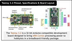
The Teensy 3.2 is a 32-bit Arduino-compatible development board designed to bring ARM Cortex processing power to hobbyists in a breadboard-friendly package. Teensy 3.2 comes with MK20DX256VLH7 MCU based on a 72MHz ARM Cortex-M4 32-bit processor. The Board comes with 64KB ram, 256KB flash memory, and 2KB EEPROM.
There are a total of 22 analog I/O pins and 34 digital I/O pins on board out of which 12 pins support pulse width modulation.
The Teensy 3.2 may be the smallest board from Teensy, but it doesn’t skimp on performance, its performance is better than the Arduino Nano which is around the same size.
Table of Contents
Specifications
These are the specifications of the Teensy 3.2 board.
| Specification | Description |
|---|---|
| MCU | MK20DX256VLH7 32-bit ARM Cortex-M4 |
| RAM | 64KB |
| Flash Memory | 256KB |
| EEPROM | 2KB |
| USB Port | USB device 12 Mbit/sec |
| CAN Bus | 1 CAN Bus present |
| I2S/TDM | 1 I2S Digital Audio |
| SPI | 1 SPI ports are available |
| I2C | 2 I2C ports are available |
| Serial Ports | 3 Serial Ports are available |
| Digital I/O Pins | 34 |
| PWM Pins | 12 |
| Analog Input Pins | 22(21 input and one is for output) |
| DMA | 16 general-purpose DMA channels |
| RTC | Yes |
| DC Current Per I/O Pin | 10mA |
| Input voltage range | 3.6V to 6.0V |
Board layout

MK20DX256VLH7 Processor: is the central MCU of the Teensy 3.2 board. This MCU runs on ARM Cortex-M4 at 72MHz.This MCU makes teensy 3.2 very faster than other development boards in this price range.
LP38691 Regulator: The LP38691 is the low-dropout CMOS linear regulator. The fixed output options for this regulator are 1.8, 2.5, 3.3, and 5V. For Teensy 3.2 we need a 3.3V regulated supply.
USB Micro-AB: Used to program and power the board.
MKL02Z32VFG4 Microcontroller: is the secondary microcontroller present on the Teensy 3.2 board. It increases the overall efficiency and performance of the board. It has a small size, ultrasmall package, and energy-efficient ARM Cortex-M0+ 32-bit performance.
This microcontroller provides:
- Run power consumption as low as 36 A/MHz in very low power run mode
- Static power consumption down to 2 μA with full state retention(fast wake-up address) and 4 μs wakeup
- Ultra-efficient Cortex-M0+ processor running at up to 48 MHz with industry-leading throughput
- Memory options include up to 32 KB flash and 4 KB RAM

- Terminal Block Breakout Board Module for Teensy 3.2, DIN Rail Mount Version. With the breakout board, you can easily extend Teensy 3.2 projects to industrial control, home automation or other applications.
- With 107 DIY solder pads on board, pitch 2.54mm, hole 0.8mm, you can use these pads to install soldered some electronic components for you need.
Teensy 3.2 pinout
In Teensy 3.2 there are a total of 22 analog I/O pins and 34 digital I/O pins out of which 12 pins support pulse width modulation. Given below are the pin diagram and pin description table of the teensy 3.2 board.


| Pin Category | Pin Name | Description |
|---|---|---|
| Power | VIN, 3.3V, Analog GND, GND | VIN – When using an external power source, this is the supply voltage pin (3.6V to 6.0V) 3.3V – The regulated output voltage (250mA max.) Analog GND – Serves as the ADC and DAC’s GND and can be connected to GND. |
| Analog Pins | A0 – A9, A14 | Pins A0 – A9 and A14 are analog pins. The default resolution is 10 bits but can be adjusted to 16 bits. Although, resolution of only up to 13 bits is practical. |
| I/O Pins | D0 – D23 | 24 Digital I/O Pins are available |
| PWM Pins | D3 – D6 D9 –D10 | 12 PWM pins |
| Inbuilt LED | D13 | Inbuilt LED connected to pin 13 |
| Touch sensing | D0 – D1 D15 – D19 D22 – D23 | These pins are for capacitive touch sensing |
| Serial Com. | TX1, RX1: Pin 0, 1 TX2, RX2: Pin 10, 9 TX3, RX3: Pin 8, 7 | Total 3 serial ports are available |
| SPI | DIN, DOUT, SCK, CS: Pin 12, 11, 13, 10 | Serial Peripheral Interface port |
| I2C | SCL0, SDA0: Pin 19, 18 SDA0, SDA0: Pin 29,30 | Inter-Integrated Circuit communication port |
| CAN Bus | TX, RX: Pin 3, 4 | CAN Bus peripherals |
Note: Digital pins on Teeny 3.2 output 3.3V i.e, support 3.3 V logic level. But accepts 5V signals as input i.e are 5 V tolerant.
How to power Teensy 3.2?
1. USB Power
Teensy is normally powered by your PC or USB hub via a USB cable. The USB power is delivered to the VUSB pin, which is linked to VIN and powers the entire board.
2. VIN Pin
When not using USB power, 5V power can be applied to the VIN pin. Because VIN and VUSB are linked, power should not be applied to VIN while using a USB cable to avoid power flowing back into your computer.
Comparing Arduino with Teensy
Given below are the differences between Arduino Nano and Teensy 3.2:
| Specification | Arduino Nano | Teensy 3.2 |
|---|---|---|
| Microcontroller/Processor | ATmega328P | MK20DX256VLH7 |
| Architecture | AVR | ARM |
| Operating Voltage | 5V | 3.3V |
| Flash Memory | 32KB of which 2KB is used by the bootloader | 256KB |
| SRAM | 2KB | 64KB |
| Clock Speed | 16MHz | 72Mhz also 16Mhz Crystal Available |
| Analog IN Pins | 8 | 21 |
| EEPROM | 1 KB | 2KB |
| DC Current per I/O Pins | 40 mA(I/O Pins) | 10mA |
| Input Voltage | 7-12V | 3.6V to 6.0V |
| Digital I/O Pins | 22 | 34 |
| PWM Output | 6 | 12 |
| Power Consumption | 19mA | 15uA |
| Weight | 7g | Around 8g |
| Price | 11 Dollars | 19 Dollars |
From these differences, it’s clear that teensy is much more powerful than Arduino nano. It has more clock frequency and Ram, a powerful processor, and much high performance than Arduino.
Schematic
Given below is the schematic of Teensy 3.2:

MK20DX256VLH7 32-bit ARM Cortex-M4 CPU running at 72 MHz is the main SMD processor mounted on the teensy 3.2 development board.
In the schematic, we can see one more microcontroller which is MKL02Z32VFG4 48MHz Cortex-M0+ Ultra-Low Power MCU having 32KB Flash, and 4KB SRAM. It is used here for signal multiplexing, decreasing wake-up time. Thus increasing the overall performance of the Teensy 3.2 development board.
MK20DX256VLH7 runs at 72Mhz but still, they added a 16Mhz external crystal oscillator to increase the overall clock frequency. The inbuilt LED of teensy is connected to pin 13. The USB port is USB Micro-AB.
Datasheet
To download the datasheet of Teensy 3.2(MK20DX256), click here.
To download the manual of Teensy 3.2, click here.
What are the different ways to program the Teensy 3.2 board?
- Arduino IDE + Teensyduino
Teensy’s primary programming environment is Arduino’s IDE software with the Teensyduino add-on. On Windows, Linux, and older Macs, Arduino is first installed, followed by the Teensyduino installer, which adds Teensy support to the Arduino IDE. Teensyduino includes a large library collection that has been tested and optimized for Teensy. Other libraries can be installed manually or automatically through Arduino’s library manager.
- Visual Micro
Visual Micro allows you to program Arduino-compatible boards, including Teensy, using Microsoft Visual Studio. Only Microsoft Windows is supported. Visual Micro is a paid commercial platform.
- PlatformIO
PlatformIO IDE is a cross-platform development environment including advanced features. Windows, Linux, and Macintosh are all supported operating systems.
- Command Line Interface with Makefile
The Teensyduino installer includes Makefiles for non-graphical use.
Teensy 4.x: {Arduino}/hardware/teensy/avr/cores/teensy4/Makefile
Teensy LC & 3.x: {Arduino}/hardware/teensy/avr/cores/teensy3/Makefile
Finally found a perfect article on Teensy