Last updated on March 16th, 2024 at 01:43 pm
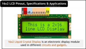
16×2 Liquid Crystal Display is an electronic display module used in different circuits and gadgets. It has 16 columns and 2 rows, which allows it to display 32 characters (16 x 2=32), each of which is built up of 5 x 8 (40) pixel dots.
The main technology behind this display is multi-segment light-emitting diodes. Using multi-segment LED we can display many characters or numbers. Since these LCD modules are inexpensive and easy to program, they are frequently utilized in DIY embedded applications.
Table of Contents

Specifications
- The operating voltage is 4.7V to 5.3V
- The operating current is 1mA without a backlight
- The display bezel is 72 x 25mm
- LED color for the backlight is green or blue
- Number of columns: 16
- Number of rows: 2
- Characters: 32
- The font size of the character is: 0.125 x 0.200 (width: height)
- It displays a few custom-generated characters
- The alphanumeric LCD display i.e. alphabets and numbers

Pinout

A 16×2 LCD display has 16 pins. Each pin serves a specific purpose, which is shown in the table below.
| Pin No. | Pin Name | Description |
|---|---|---|
| Pin 1 | Ground | This is the ground pin of the LCD |
| Pin 2 | VCC | This is the supply voltage pin of the LCD |
| Pin 3 | VEE | Adjusts the contrast of the LCD |
| Pin 4 | Register Select | Toggles between Command/Data Register |
| Pin 5 | Read / Write | Toggles the LCD between Read/Write operation |
| Pin 6 | Enable | Must be held high to perform Read/Write operation |
| Pin 7 – 14 | Data Pins | These pins are used to send commands or data to the LCD |
| Pin 15 | LED Positive | Normal LED-like operation to illuminate the LCD |
| Pin 16 | LED Negative | Normal LED-like operation to illuminate the LCD connected to ground |
Back Side of 16×2 LCD

On the back side, we can see some circuits. Let us understand the purpose of each in detail.
It becomes a complicated task to configure everything using a microcontroller. Therefore, an Interface IC like the HD44780 is employed and put on the LCD Module’s backside. This IC’s job is to receive commands and data from the microcontroller and process them so that relevant data can be displayed on the LCD screen. A few complimentary resistors are also used with the LCD controller.
There are some empty footprints on the PCB module. The charge pumps circuits like the ICL7660 or MAX660 are intended for use with these footprints.
The Rosc typically has a value of 91K Ohms at 5V VCC. Its value gets modified when any timing issues or problems occur with command execution.
Read also: 74HC595 Pinout, Specs, Working, and Datasheet
Commands used to drive 16×2 LCD
Prior to connecting a 16×2 LCD to any microcontroller, the LCD needs to be initialized. We must send certain commands to do that. Similarly, we must send commands to clear the display or change the cursor position. In short, we may say that commands are used to drive LCD16x2.
Commonly Used LCD 16×2 Commands
| Hex Code | Function |
|---|---|
| 0F | Turn ON the display and Cursor |
| 01 | It will clear the screen |
| 02 | The cursor will return at (0,0) position |
| 04 | It will shift the cursor to the left |
| 06 | It will shift the cursor to the right |
| 05 | The display will shift to the right |
| 07 | The display will shift to the left |
| 0E | The display will be ON and the cursor will start blinking |
| 80 | It will force the cursor to start at the beginning |
| C0 | It will make the cursor start from the second line |
| 38 | Forms 5×7 Matrix with 2 lines |
| 83 | Brings the cursor to the first line but in the third position |
| 3C | It will activate the second line |
| 08 | It will turn the display and the cursor OFF |
| C1 | It will make the cursor jump to the second line but at the first position |
| 0C | The display will be ON but now there won’t be any cursor on the screen |
| C2 | It will make the cursor jump to the second line and at the second position |
What is the use of RS (Register Select) Pin?
We use the register select pin to change from one register to another. In a 16×2 LCD, Command, and data registers are used. RS is equal to zero for the command register and one for the data register.
Command Register in 16×2 LCD
The command instructions sent to the LCD are stored in the command register. An LCD receives a command when instructed to carry out a certain operation. Examples:
- Clearing Screen
- Setting cursor position
- Initializing LCD etc.
Note: The command register is where commands are processed.
Data Register in 16X2 LCD
The data that will be displayed on the LCD is kept in the data register. The character’s ASCII value, which will be displayed on the LCD, is the data. Data is processed in the data register before being sent to LCD. The data register is chosen when RS=1.
16×2 LCD datasheet
Given below is the datasheet of the 16×2 LCD by Adafruit. You can download it from here.

Note: Please refer to the manufacturer specific datasheet of the LCD.
What are the Dimensions of 16X2 LCD

This 16×2 LCD display has a maximum thickness of 13.2 mm with outline dimensions of 85.0 x 30.2 mm and VA(Vertical Alignment) 64.5 x 16.0 mm, respectively.
Applications of 16X2 LCD
A 16×2 LCD can display numbers as well as characters. That’s why it is used in a variety of applications. Some of them are: Calculators, Weighing scales, BMI machines, DIY projects, etc.