Last updated on January 6th, 2026 at 11:13 am
Arduino Uno is one of the most popular Development boards of our time. It can be used for almost any project that one can think of. But sometimes before making an actual circuit, it is a good idea to simulate that circuit first.
Simulating the circuit firsthand can save you from a lot of trouble. Proteus is one of the software that does this job brilliantly. And now you can simulate an Arduino in proteus before even implementing it in actual hardware. By the end of this post, you will know how to make Arduino projects in proteus.
Watch the video tutorial here:
Table of Contents
Steps to add Arduino library to Proteus
STEP 1: First of all download the Arduino Library from the link given below.
STEP 2: Download this file to the desktop of your PC.
STEP 3: Unzip the .zip file to the desktop of your PC.
STEP 4: Copy the two obtained files from the desktop.
STEP 5: Go to C:\Program Files (x86)\Labcenter Electronics\Proteus 7 Professional\LIBRARY
Note: In case you can’t find the Library folder in Proteus 8, first unhide the hidden items from the view menu. Then Go to—-> C:\ProgramData\Labcenter Electronics\Proteus 8 Professional\LIBRARY
STEP 6: Paste the files here and you are done!
STEP 7: To use the Arduino boards, open proteus and click on “pick from libraries”
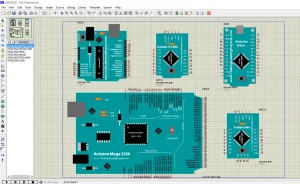
STEP 8: Search for “Arduino”, you will see 6 Arduino boards in the component section. Select the board of your choice and start simulating!
Read also: Ultrasonic sensor library for proteus.
Arduino projects in proteus
Project 1: Led blinking
STEP 1: Place these components on the sheet and connect them as shown below.
- Arduino UNO
- Resistor(100 ohm)
- LED
- Ground(from Terminals section)

STEP 2: Copy this “LED blinking” program to your Arduino IDE:
void setup() {
pinMode(13,OUTPUT);
}
void loop() {
digitalWrite(13,HIGH);
delay(1000);
digitalWrite(13,LOW);
delay(1000);
}STEP 3: Go to preferences

STEP 4: Check “Compilation” CheckBox

STEP 5: Click on verify (compile)

STEP 6: After compiling, copy the HEX file path from the bottom corner as shown below.

STEP 7: Open the proteus window, and double-click on Arduino to open the settings. Paste the file path in the “Program File” section and click ok.

STEP 7: Run the simulation! Led at pin no. 13 will blink.
Project 2: Controlling LED brightness from a potentiometer
STEP 1: Place these components on the sheet and connect them as shown below.
- Arduino UNO
- Resistor(100 ohm)
- LED
- Potentiometer
- DC 5 V(from Generators section)
- Virtual terminal(from Instruments section)
- Ground(from Terminals section)

STEP 2: Copy this program to your Arduino IDE:
int y;
int x;
void setup()
{
pinMode(10,OUTPUT);
pinMode(A0,INPUT);
}
void loop()
{
Serial.begin(9600);
x=analogRead(A0);
y=map(x,0,1023,0,255);
analogWrite(10,y);
Serial.print("INCHES");
Serial.println(x);
delay(500);
}The rest of the steps from 3 to 7 are the same.
STEP 8: Run the simulation and open the virtual terminal.
STEP 9: Change the potentiometer’s wiper terminal position to control the brightness of the LED. On the virtual terminal, you will see the analog input values from the potentiometer.

thanks but i can’t use in ARES
can you give the PCB footprint?