Last updated on February 8th, 2025 at 11:01 am
This is your step-by-step guide to Arduino IoT Cloud Tutorial in 2024. As an example, you will learn how to control the status of an LED via the Internet.
To get started with Arduino IoT Cloud, you’ll need a microcontroller board with WiFi compatibility. I have an Arduino UNO R4 WiFi here. You can use any other Arduino board like Arduino Nano 33 IoT OR other non-Arduino boards such as ESP32.
Table of Contents
In your first project, you will control an LED directly through the internet. So to build it just follow these steps.
Step 1: Set up your board
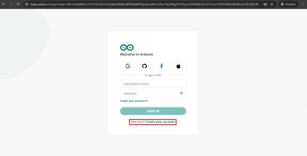
First, go to “cloud.arduino.cc” and sign up for a new account.
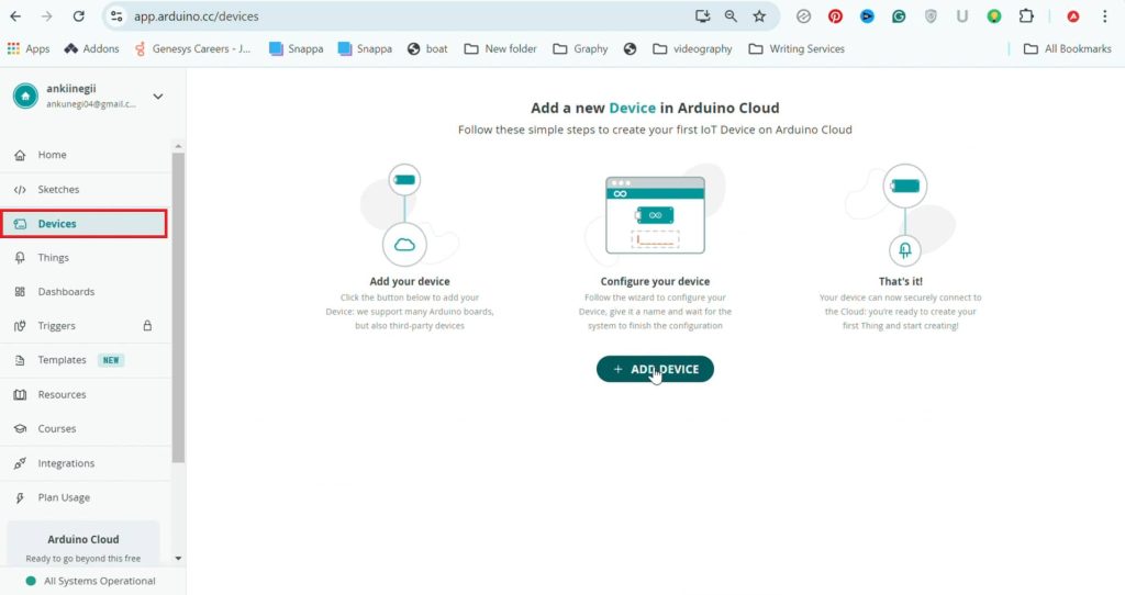
Once you’re inside your account, go to “Devices” and click on “Add Device.”
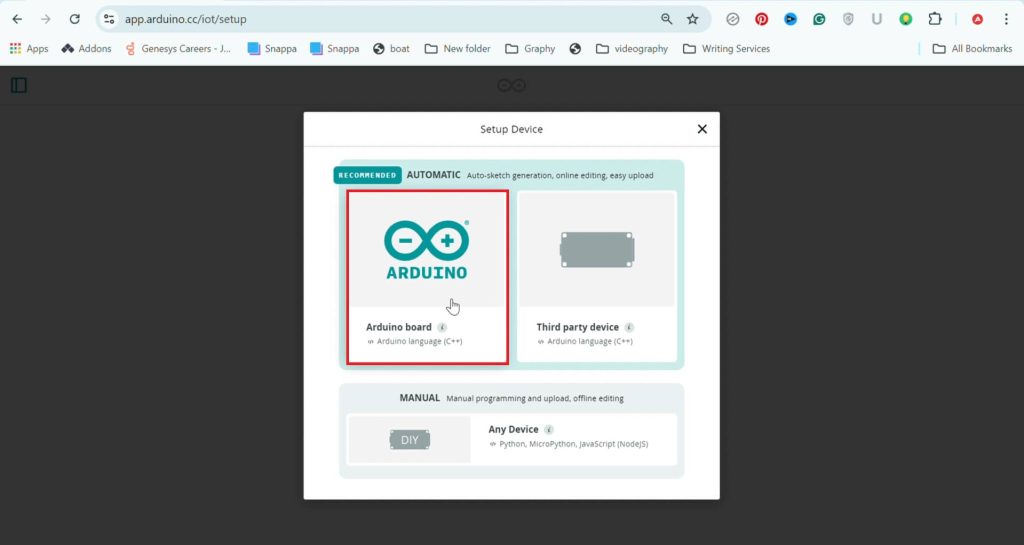
Now, select your board type. Since I’m registering the UNO R4, I’ll choose the first option. For the ESP32 or any other non-Arduino board, select the second option.
Next, we need to install the cloud agent on your system. Click on “Install,” then “Download.” Once installed, you’ll see a prompt. Close this tab and connect your board to the system.
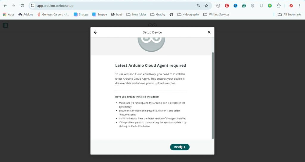
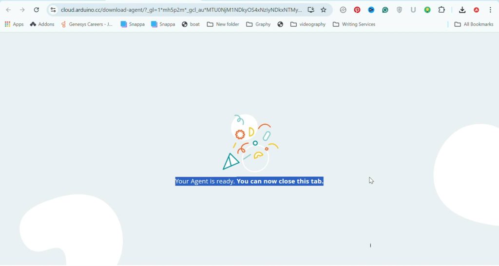
Once your board—UNO R4 WiFi in my case—is recognized, we need to configure it.
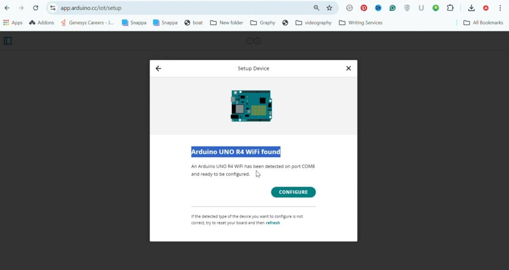
This process can take up to 5 minutes, or sometimes even longer.
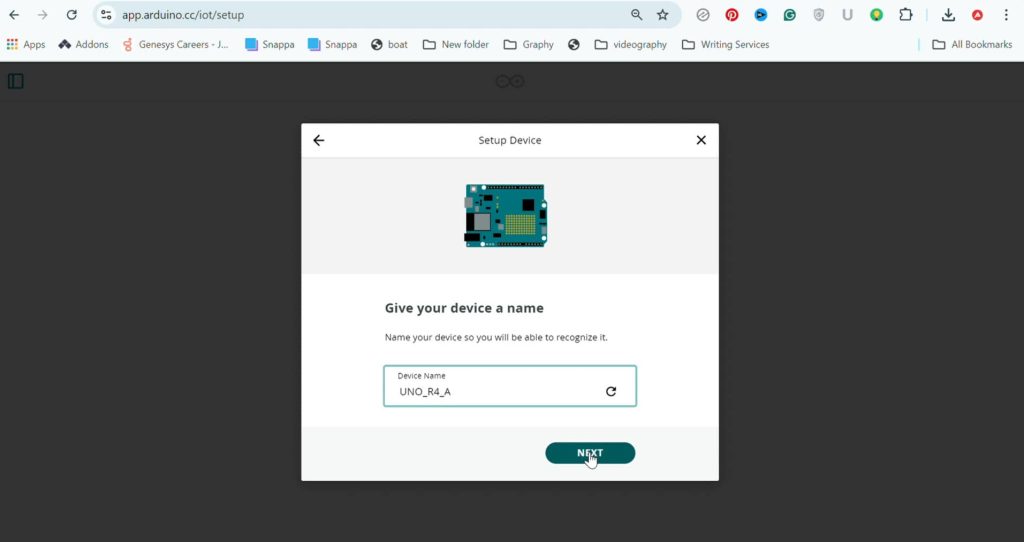
Give your device a name and click “Next.” When the setup is complete, you’ll get a message. Click “Done,” and you’ll be redirected to the homepage.
To check whether your device is registered, go to the “Devices” section. Here’s my board name, but it’s still offline. Let’s move on to the next step.
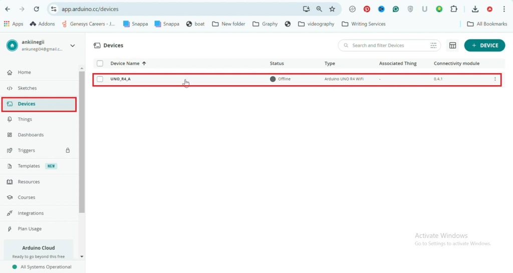
Step 2: Create your project
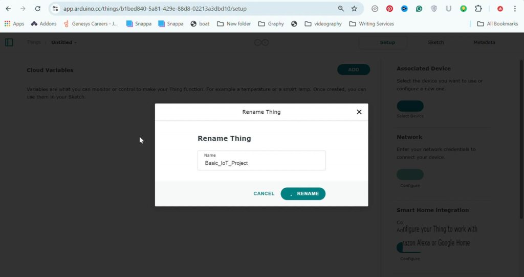
Go to the “Things” section. Click on “Create Thing” and give your project a name.
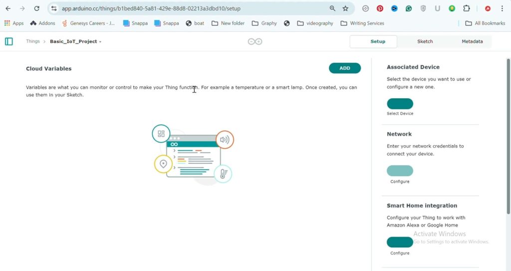
To create your first cloud variable—something I’ll explain in a bit—click on “Add.”
Give the variable a name; in my case, it’s “LED_State.” Now This step is crucial, so pay close attention: Choose the type of variable—in this case, Boolean. Why Boolean? Because the state of the push button can either be 0 or 1.
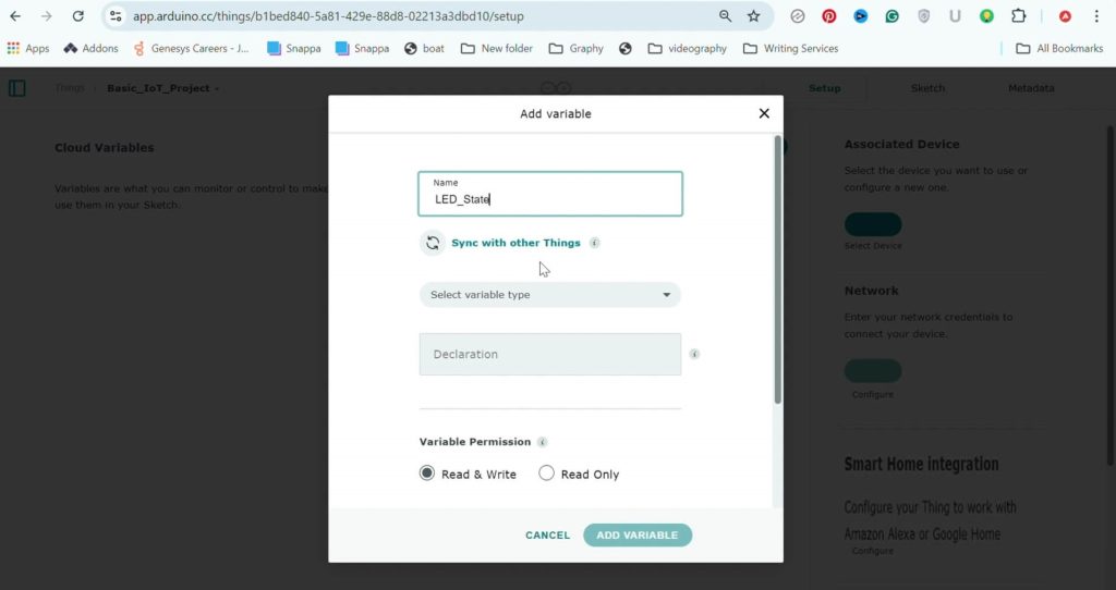
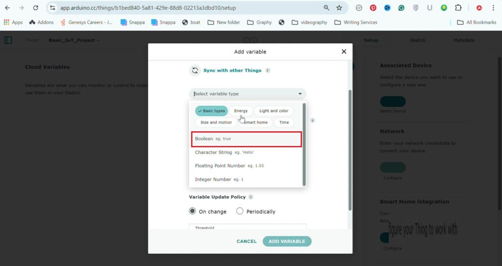
Next, select the “Read and write” option because we want to control the LED. Use the “Read-only” option only when the variable is linked to input data, such as sensor readings.
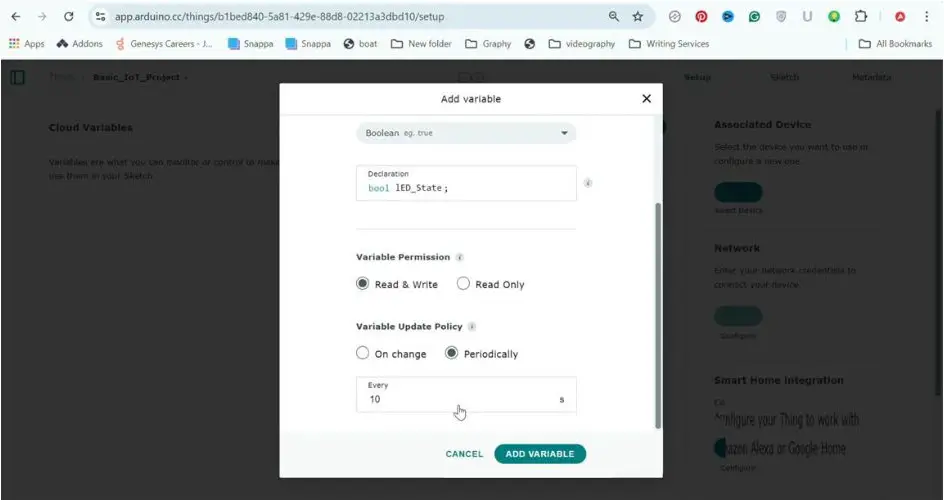
Next is the “Variable update policy,” which simply means: Do you want the variable to be updated only when there’s an actual change, or do you want it to be updated periodically, like every 10 seconds? If we were reading a sensor, the periodic update would be the right option. But here, we’ll select the “On Change” option and click “Add Variable.”
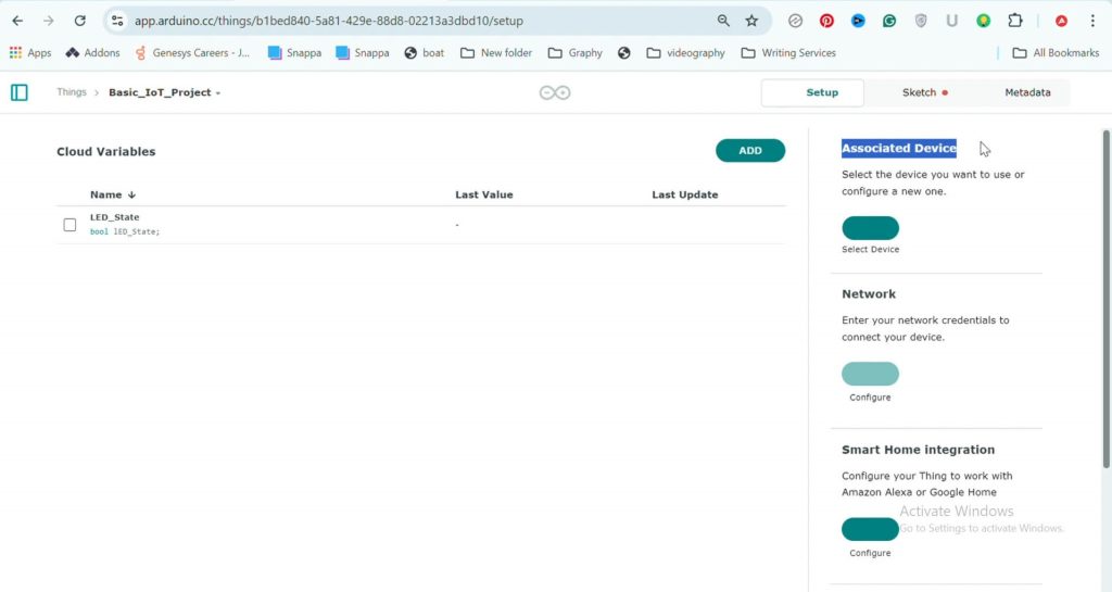
You’ll see the variable listed here. Now, click on “Select Device” to link the board to the variable. When you see the board name, click on “Associate.”
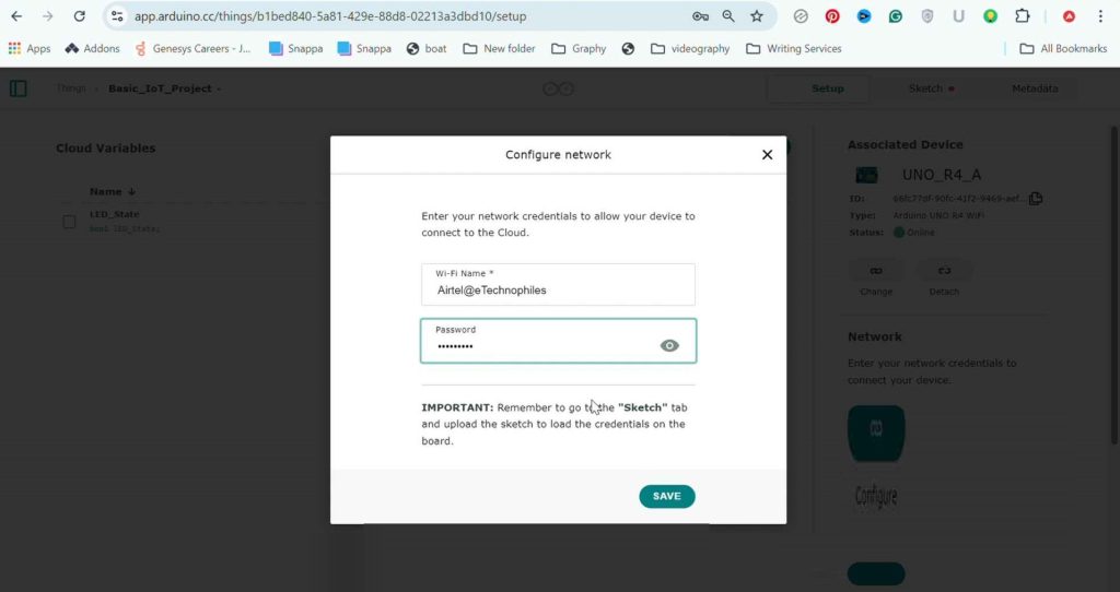
Next, enter your network credentials to connect the board to the internet and click “Save.”
Step 3: Create your dashboard
So, we’ve created a cloud variable named “LED_State.” Now, we need to create a visual control for it, such as a push button.
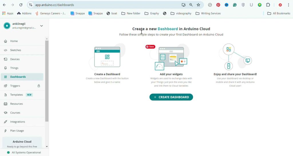
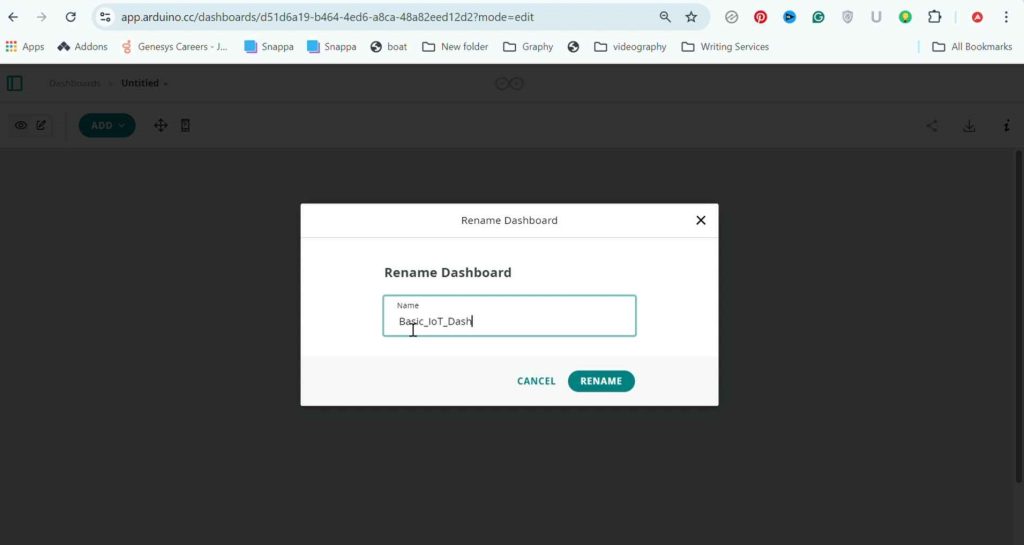
Go to the “Dashboard” section, click on “Create Dashboard,” and give your dashboard a name.
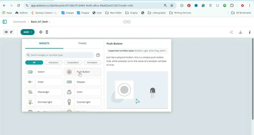
To create your first widget, click on “Add.” You’ll see tons of different widgets, but all we need right now is a push button. This visual push button should be linked to the variable we created. Select it and click on “Link Variable.” Now, whenever I press this push button, the value of the cloud variable changes.
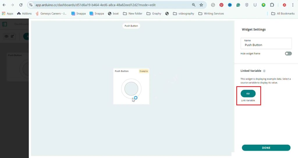
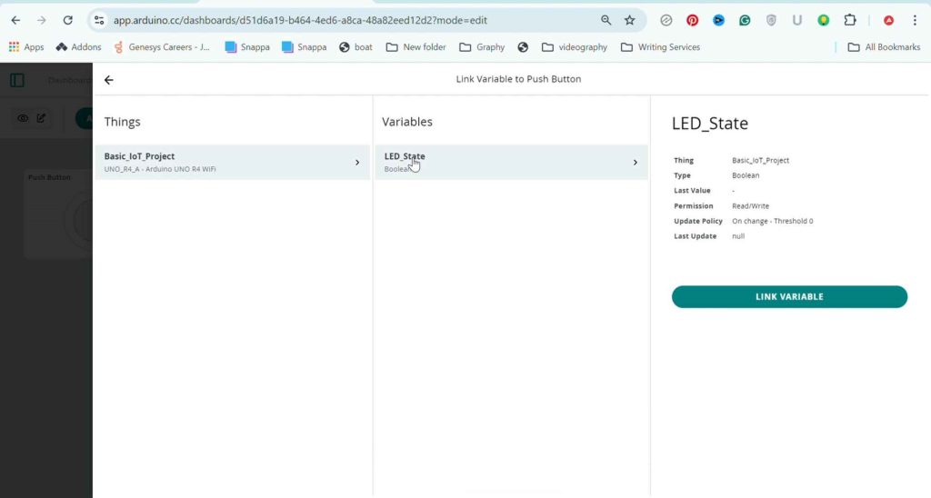
But nothing will happen because we still need to program our board for this to work.
Step 4: Sketch
Go to the “Things” section, select your thing, and click on “Sketch.” This is the default sketch created by Arduino, and we’ll need to make some changes to it.
I made the necessary final changes to the program so that whenever the push button on our IoT dashboard is pressed, the LED on pin 13 turns on.
Step 5: Upload the code from Arduino software
To upload the sketch directly from here over the internet, you’ll need a paid plan. If you’re on the free plan, follow these steps:
1. Open the IDE on your system and log in to your cloud account. Once done, you’ll see all your sketches here. To download the sketch we just created, click on “Pull Sketch” and open it.
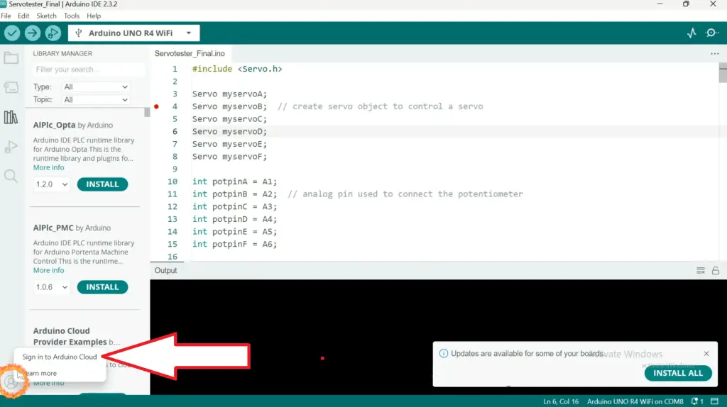
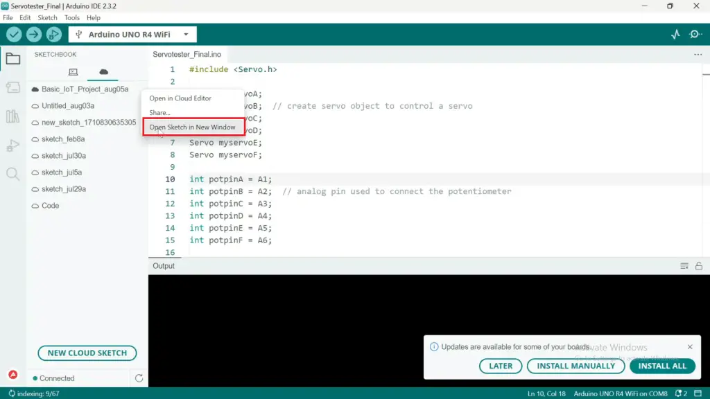
2. Now we have to upload the program manually to our board. But first, let’s hook up an external LED to digital pin 13.
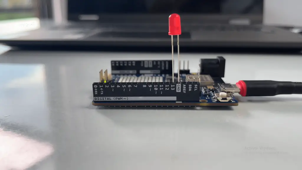
3. Okay, now upload the code.
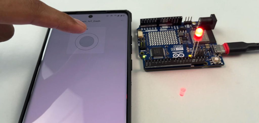
Once the code is uploaded successfully, open your IoT dashboard and press the button. As you can see, the LED is working as intended.
Note: You can also use the app to access your dashboard. The app in the App Store is: “Arduino IoT Cloud Remote“. In Play Store: “IoT Remote“
When I press the push button, the cloud variable value changes to 1. When it changes, the function is called, and the LED turns on as the LED_State variable is 1. When I release the button, the cloud value changes to 0, and again the function is called, but this time the LED turns off as the variable is 0.
Similarly, you can control many different outputs, such as a servo motor, where a slider controls the servo position. You can also read sensor readings and plot a graph, for example, the readings from an LDR sensor attached to a plant in your home.
