Last updated on February 22nd, 2024 at 02:09 pm
Ever since I started learning electronics I always wanted to build my own LED Cube. But neither I have the time nor in-depth knowledge of electronics required to build one. Then I recently got an mail from Banggood.com asking me to review any Arduino- Microcontroller-related kit.
So while going through their products, I found this DIY LED CUBE KIT which has an additional Music mode feature.


So here I was, assembling the kit in front of the camera 20 days after placing the order. Overall this was a fun project to do, and here is my unbiased review of this DIY kit. Read this article and then decide for yourself whether you should buy one or not!
It took me a lot of time to figure out how to assemble this kit step by step. So in this post, I am also going to give step-by-step instructions on “how on earth this kit is assembled”!
Note: It took me 16 hours to assemble this kit, So you need to have a lot of patience. But overall, this is a fun project to do, and you can learn a lot while assembling the kit.
Unboxing
As I have already mentioned, I got this product from a China warehouse at my doorstep 20 days after placing the order with Banggood.com. Although there was no box, the packaging was good, having three-layer protection:


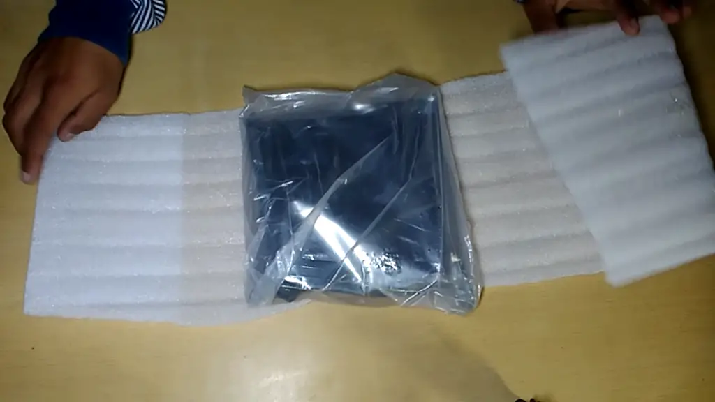
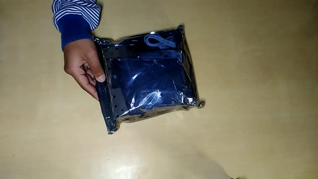
All components were placed properly inside this Airtight thick container:
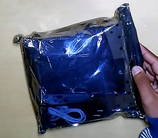
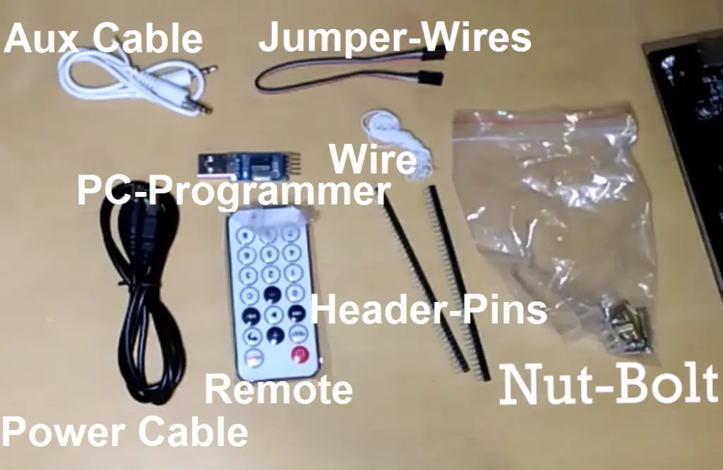
The package contains:
- LED Packet
- Acrylic Sheet
- Main Board
- Another small pouch
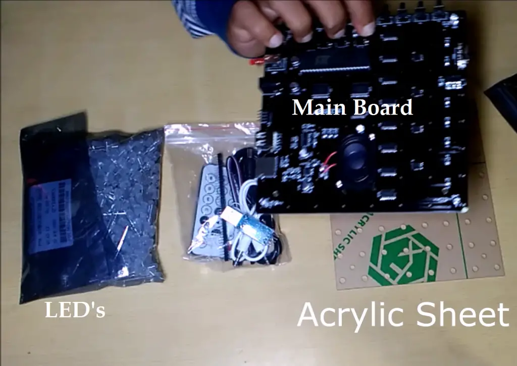
Small Packet contains other necessary components:
- Power Cable
- Remote
- Header Pins
- Aux-Cable
- PC-Programmer
- Jumper-Wires
- Connecting Wires
- Nut-Bolt
Though it’s easy to assemble the kit(step by step), the instruction manual provided is in horrible English. And on top of that manual is not organized well. You can’t just really read the manual and start building the Cube right away.
You will have to watch many videos to get the hang of Instructions like I did. But no worries; if you have decided to buy this kit, you can find all the instructions (step by step) in this post.
Step by Step Assembly instructions
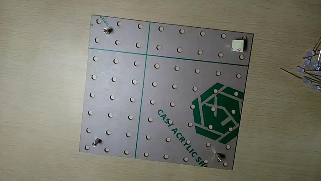
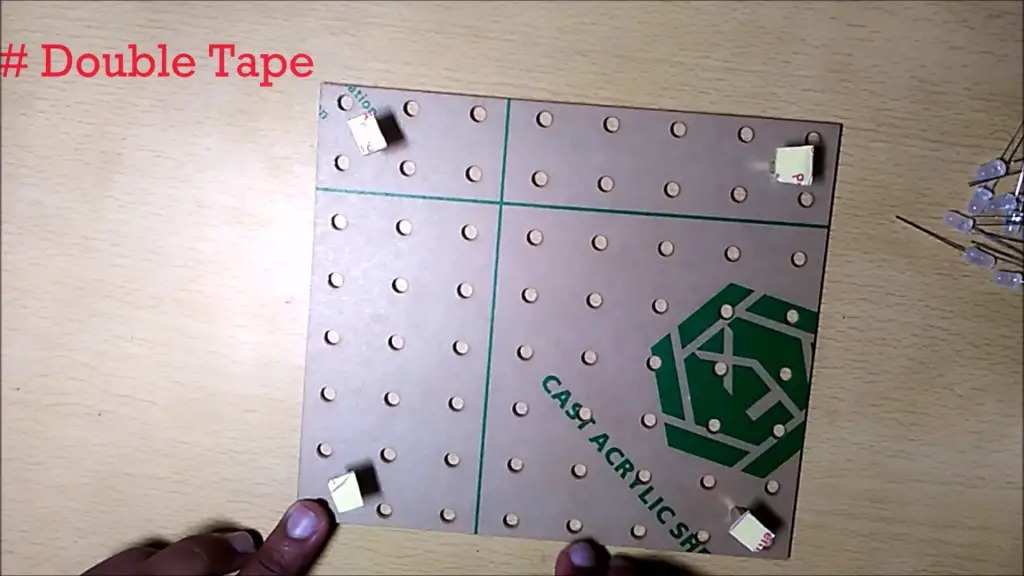
Step 1: Screw the spacers on the Acrylic sheet and then use double tape for stability.
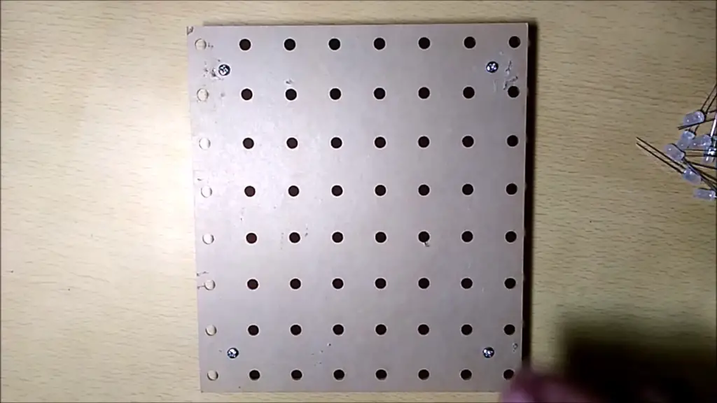
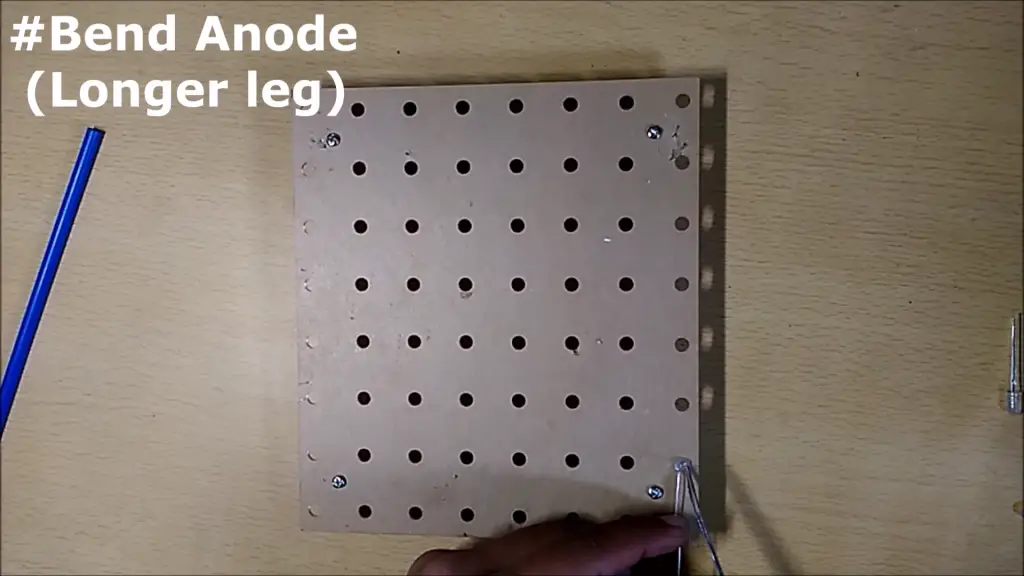
Step 2: Bend the Anode(longer leg) towards you after placing LEDs on the Acrylic sheet.

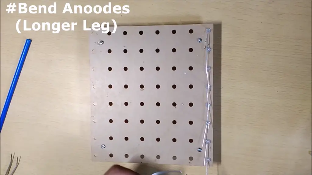
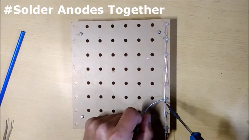
Step 3: Solder all anodes together one by one
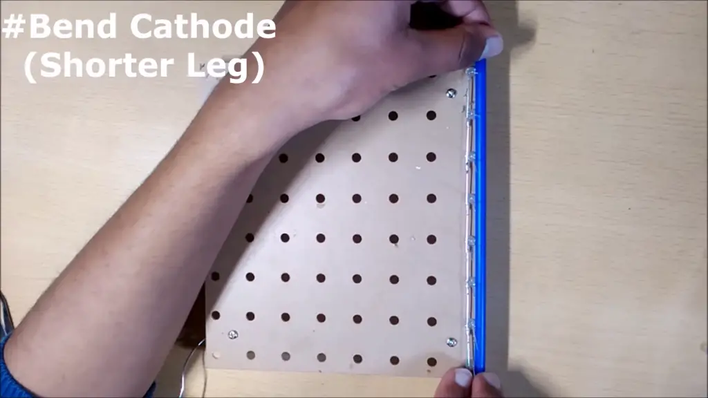
Step 4: Bend all cathodes(Shorter leg) to the right using a straw
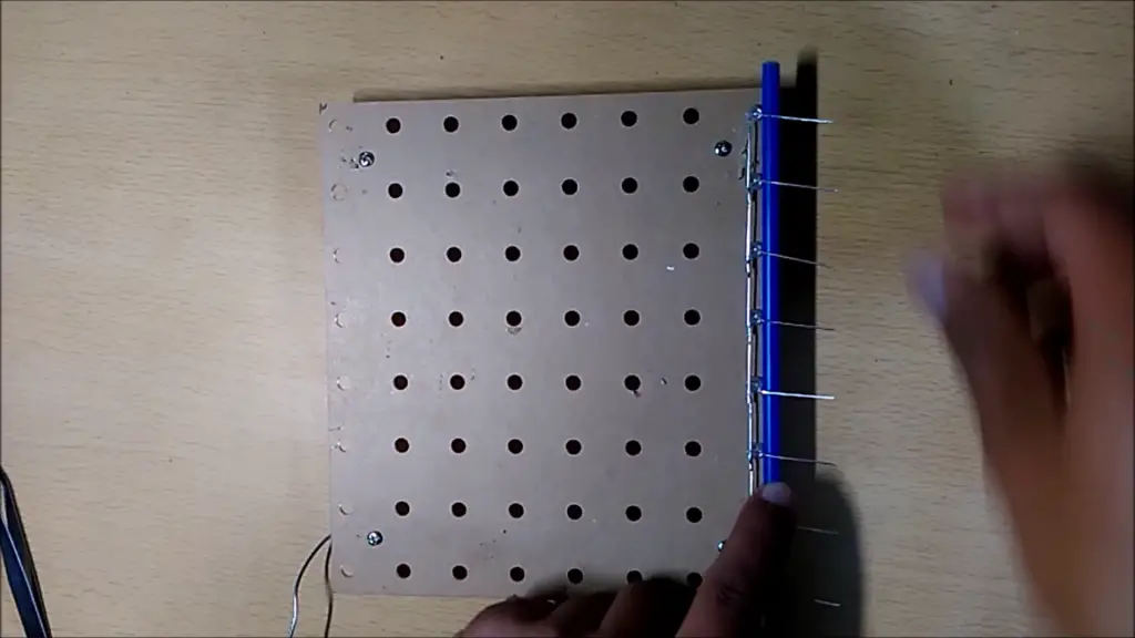
Step 5: Repeat all the above steps for the second column
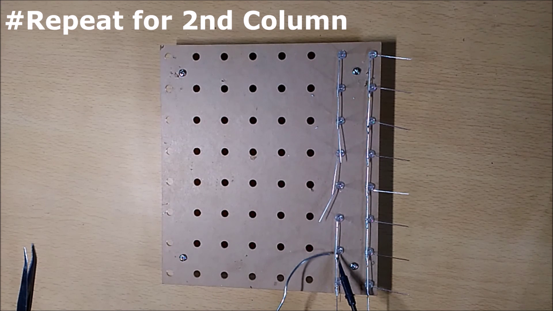
Step 6: Solder Cathode of second-row LEDs with the first-row cathodes

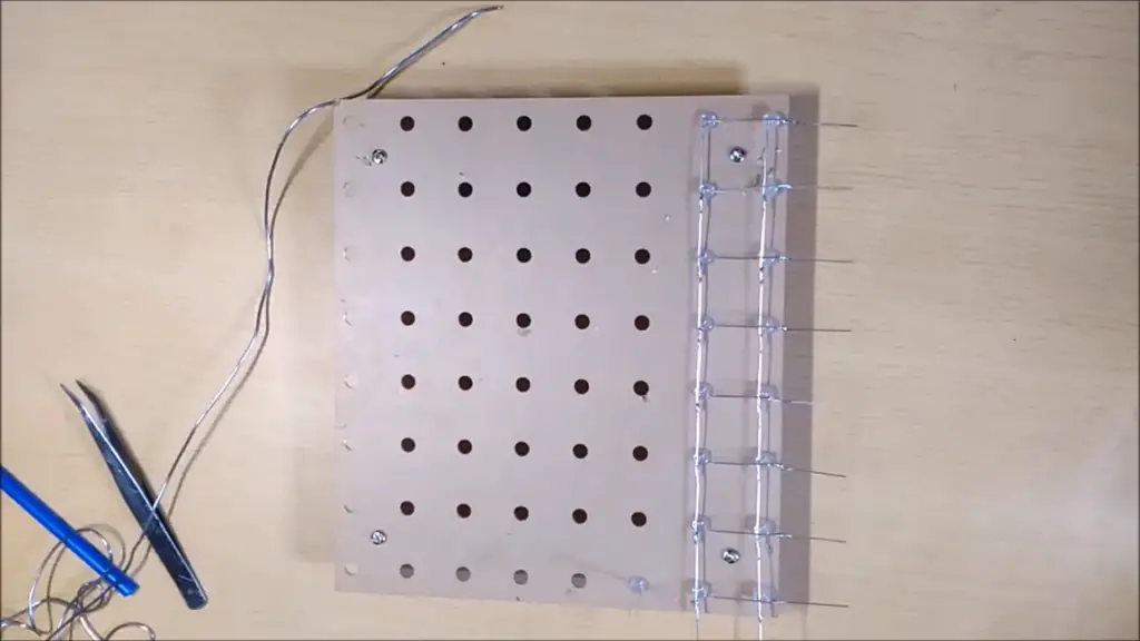
Step 7: Repeat the above steps for the remaining columns
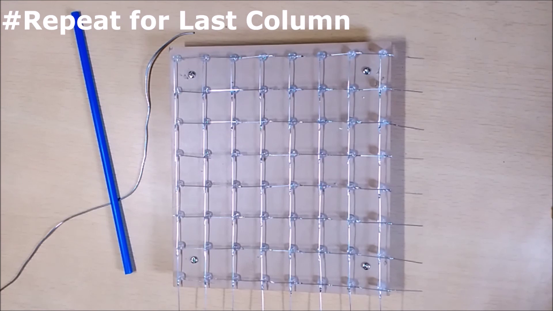
Step 8: Double-check each LED using a 3-volt supply. It is better to check LEDs right now else it would be difficult later.
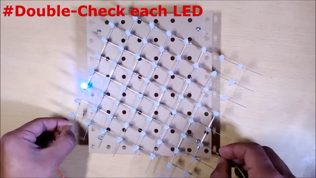
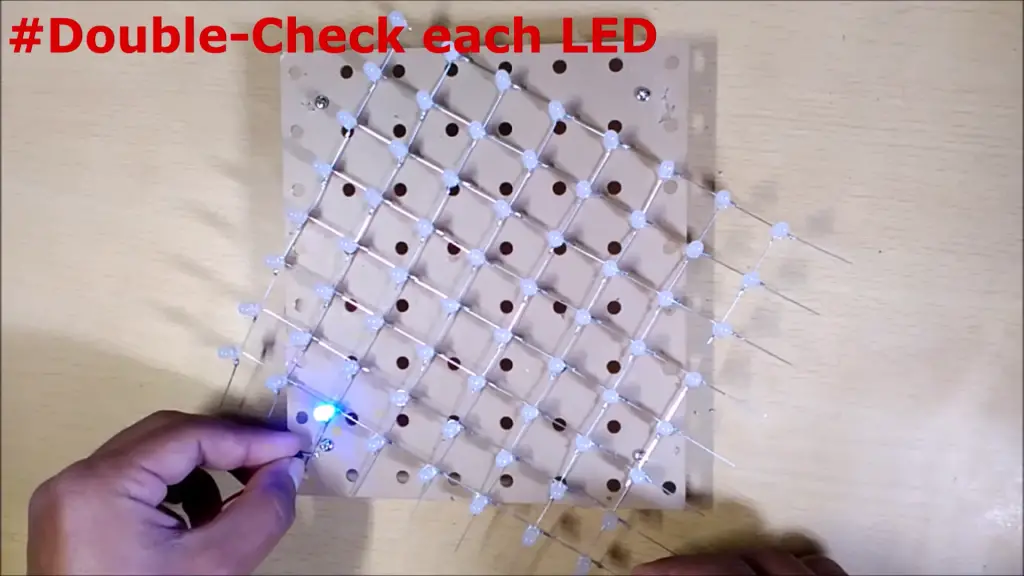
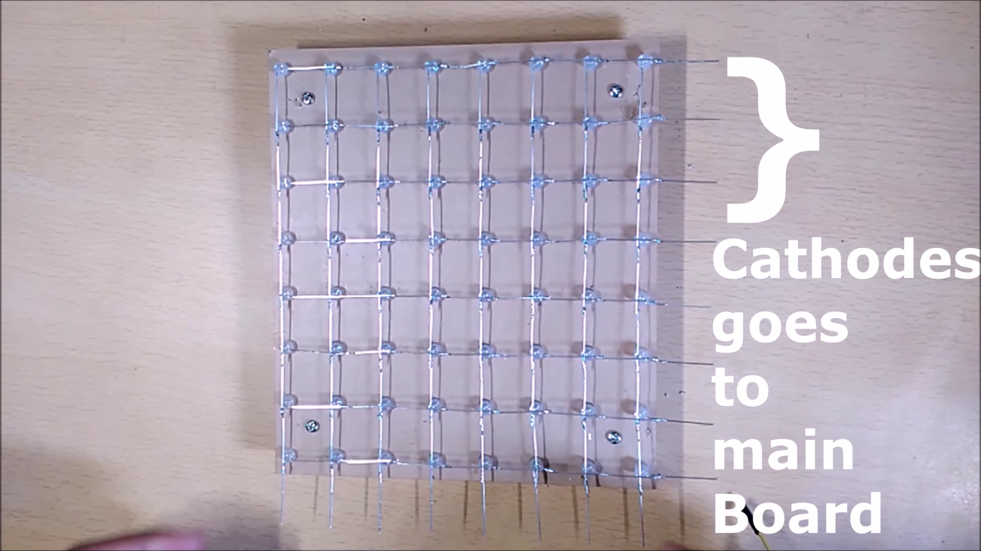
Step 9: Remember that the cathodes of each grid go to the main board and not the Anodes
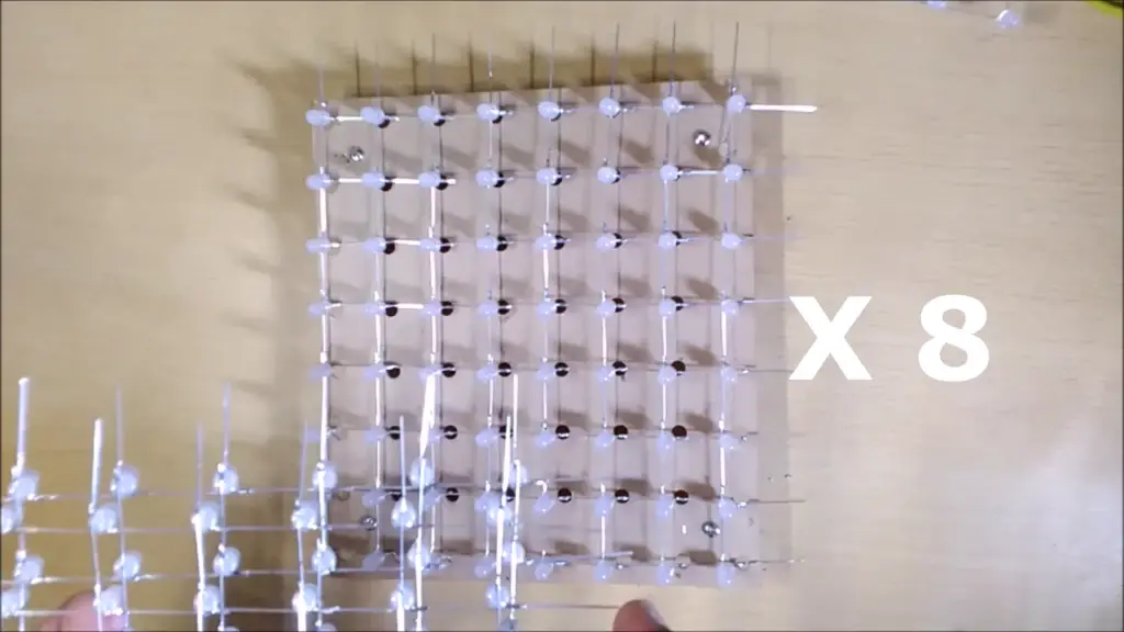
Step 10: Repeat the same process to build 7 more LED Grids

Step 11: Cut out the header pins and solder them on the main board, as shown in the slideshow below.
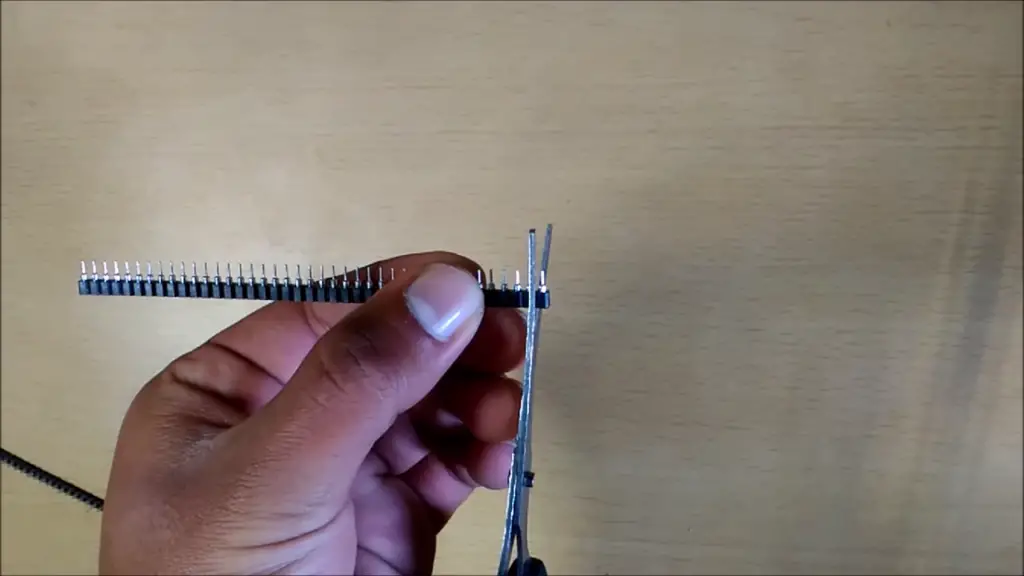
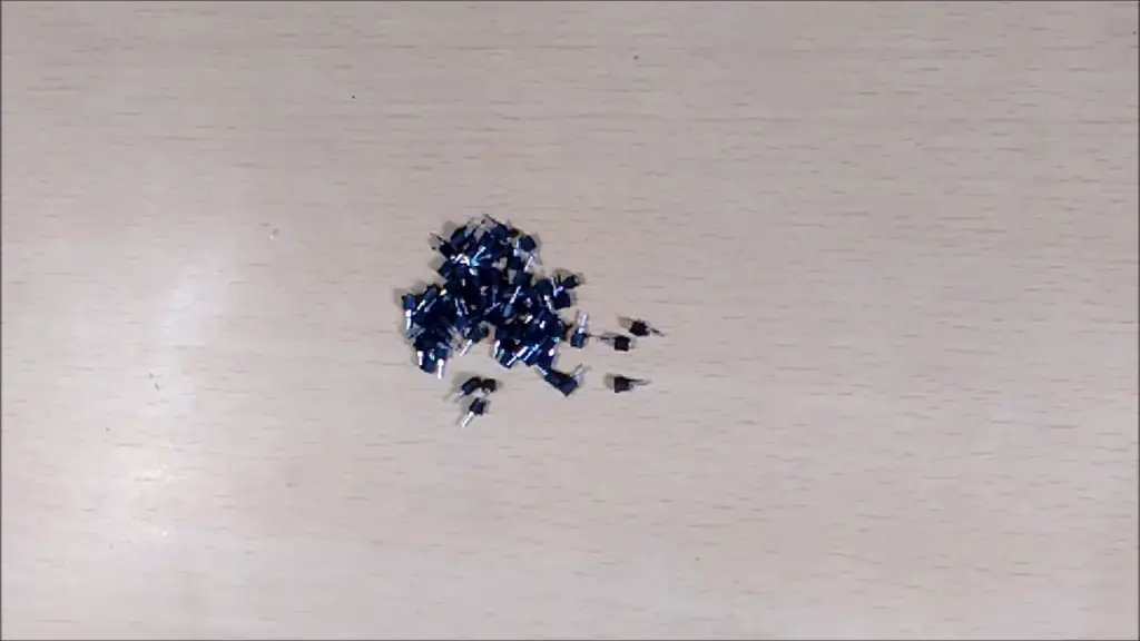
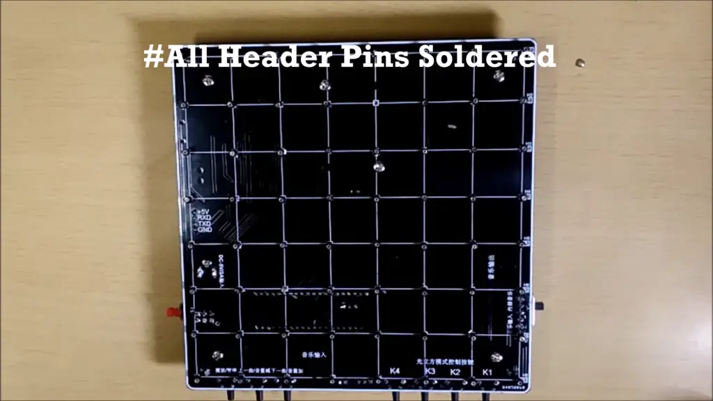
Step 12: Bend Anodes away from the LED’s head, as shown in the figure below
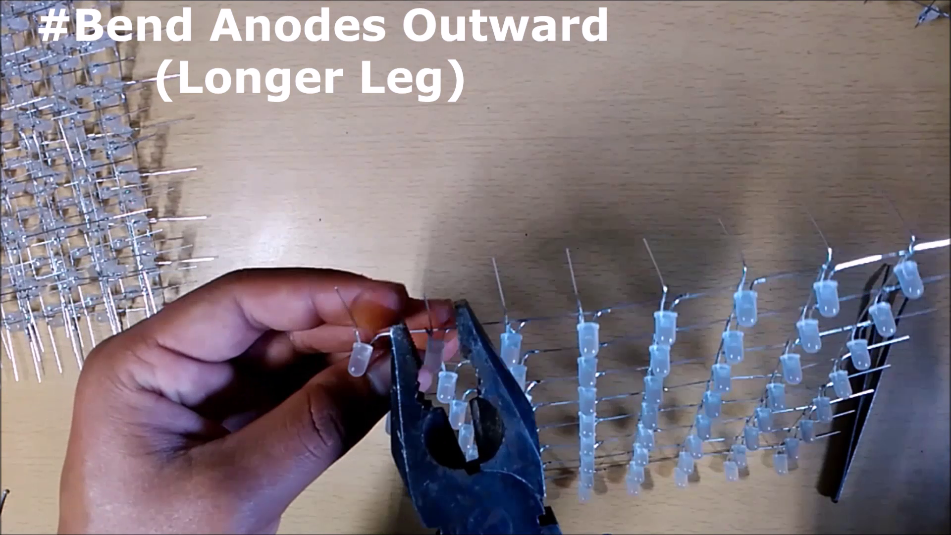
Step 13: Place the LED Grid on the Main Board from the Cathode side towards the Keys


Step 14: Solder anodes of each Grid together(Side by Side)
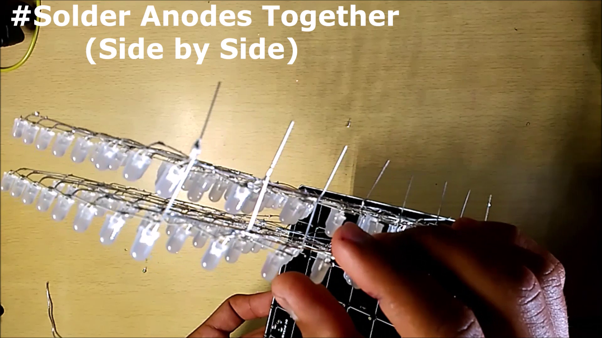
Step 15: Repeat all the above steps for the remaining Grids
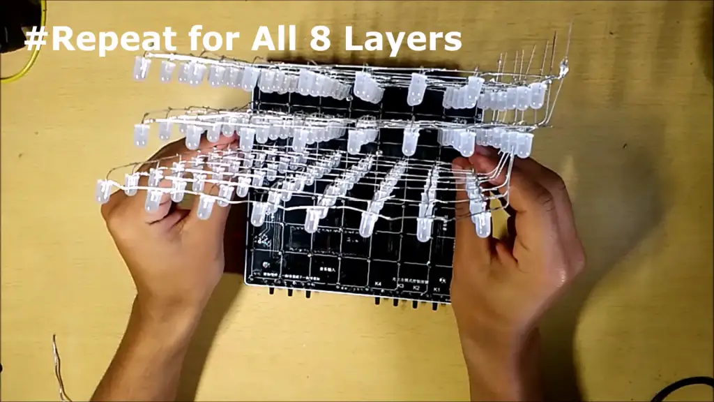
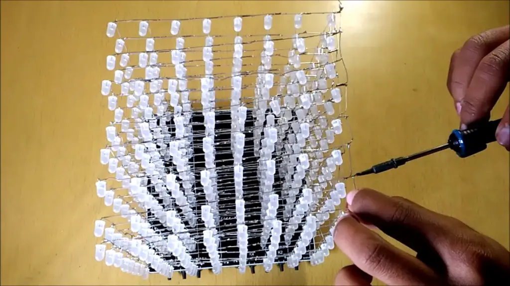
Step 16: Cube at this stage
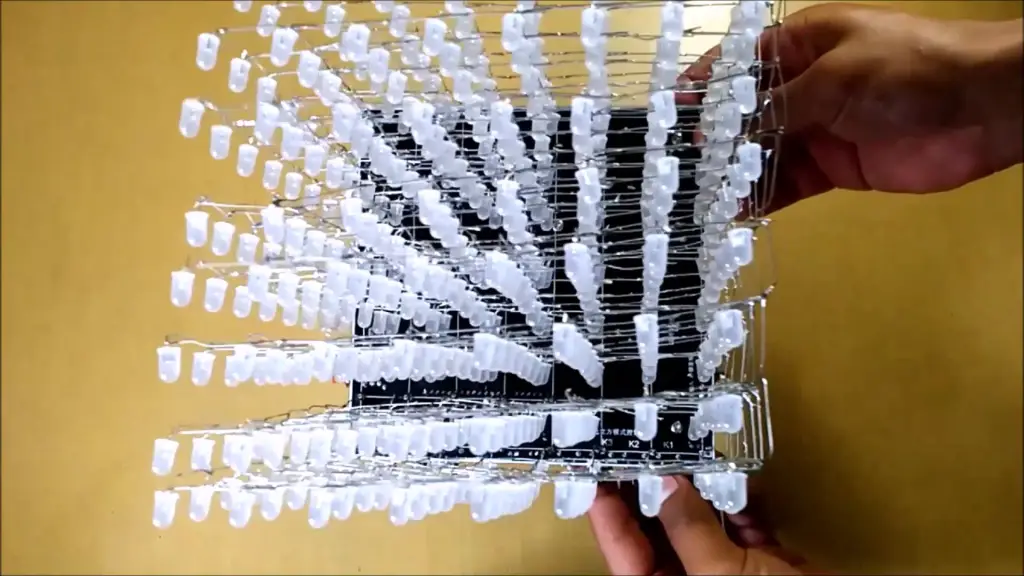
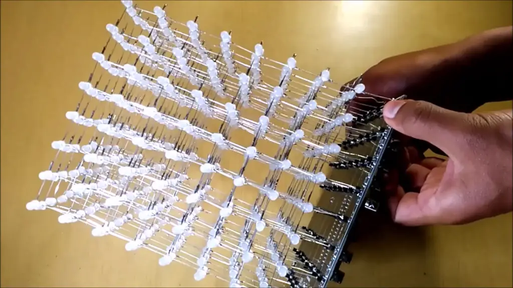
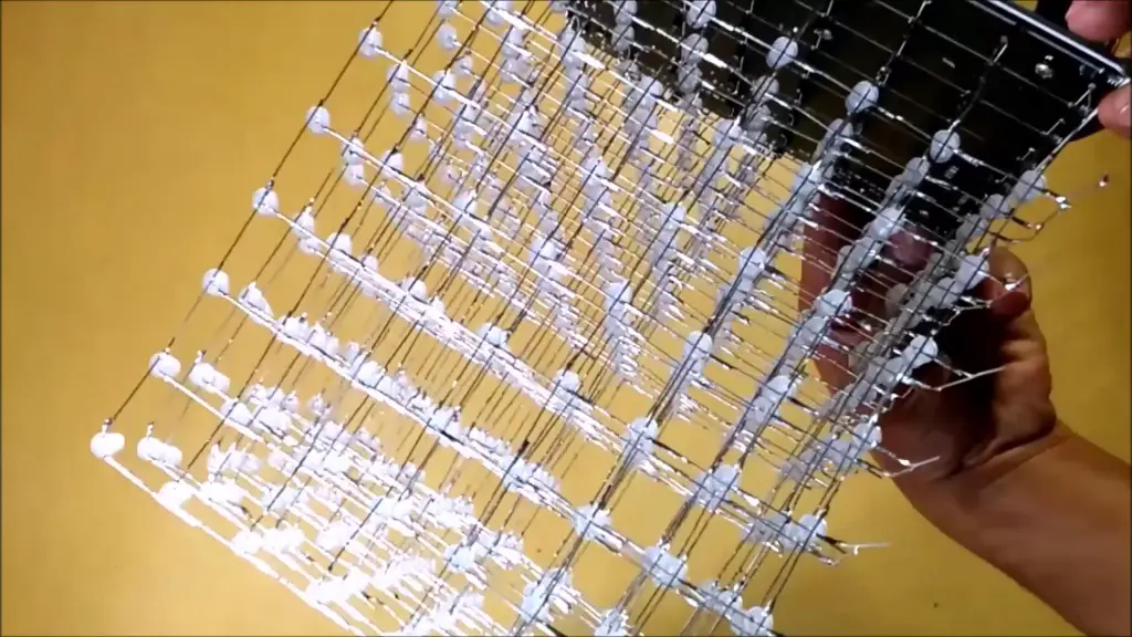
Now since the cathode portion is completely connected to the board, it’s time to connect the Anodes using a Connecting wire.
Step 17: Connect the first Anode row(bottommost) to the first +ve terminal and then the Corresponding Anode row to the last row(Topmost) as shown in the slideshow below
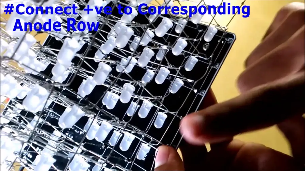
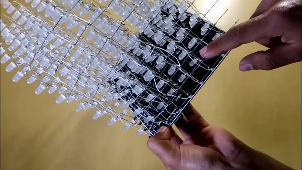
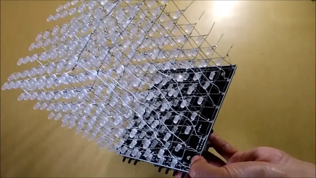
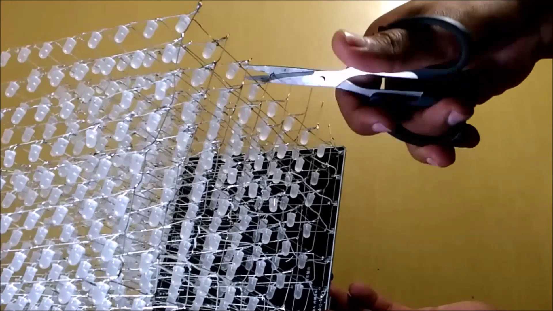
Step 18: Cut out the extra portion that’s left as shown below
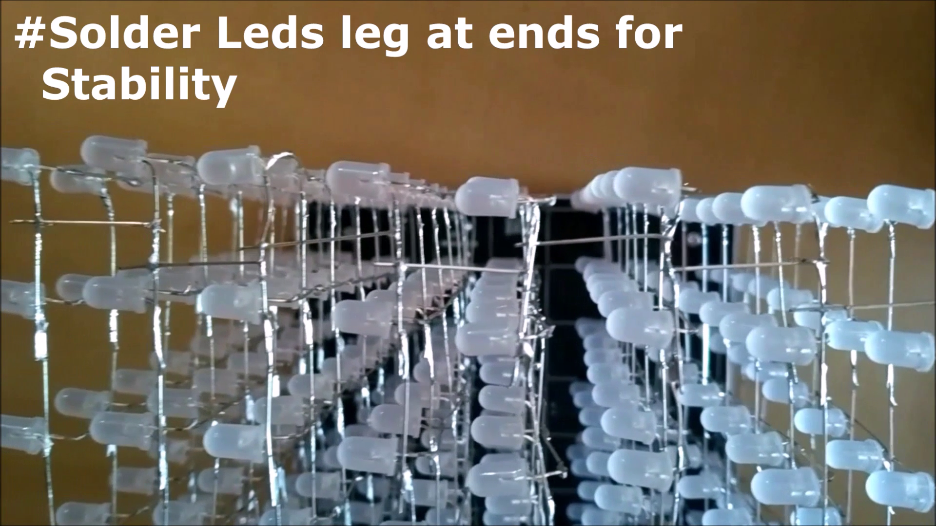
Step 19: To make this structure more stable, I soldered each grid end to the closest grid’s end using a cut-out portion from above
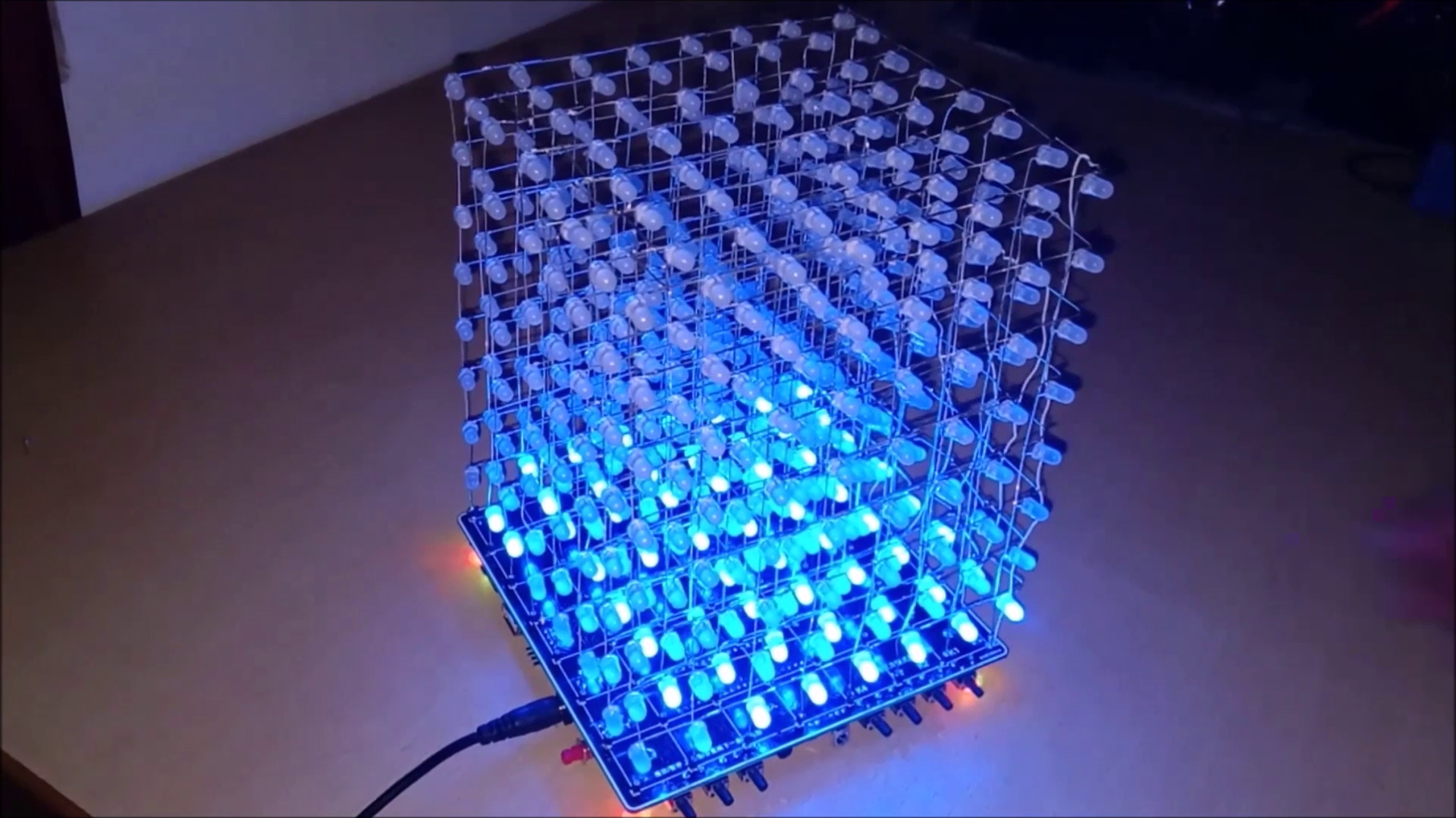
Step 20: Now just connect the board to the 5v / 2Amp supply using a power cable and switch on the board
Assembling time and final Impression:
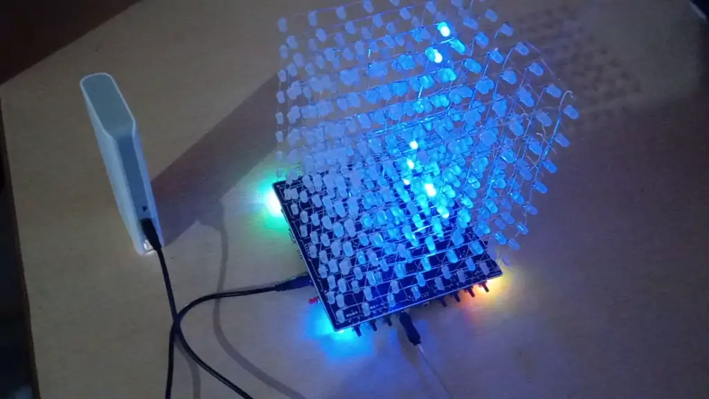


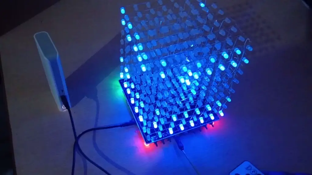
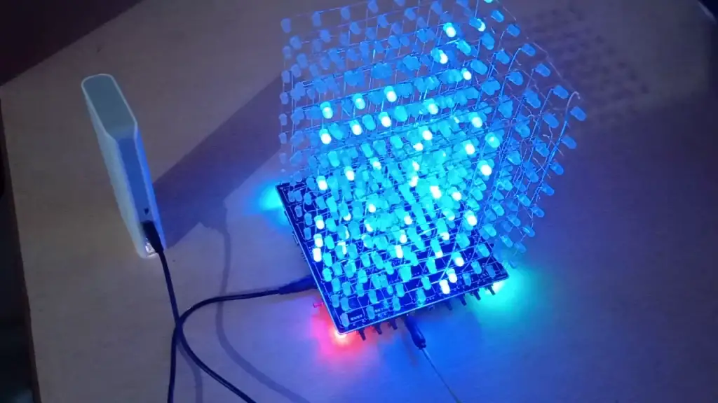

Since I really had no idea then of how the kit was assembled, it took me almost 16 hours(without break) to complete this project. But you can finish this project in just 8 hours if you follow the instructions given below.
The only thing that consumed my time while assembling the kit was soldering joints because there was nothing else to do from beginning to end. If you are a beginner then this kit is best for you to improve your Soldering skills.
As I always wanted to have my own LED Cube, I felt overwhelmed after finishing the project. There are a total of 42 eye-catching animations that start running as soon as the LED Cube is powered, some of which are outstanding.
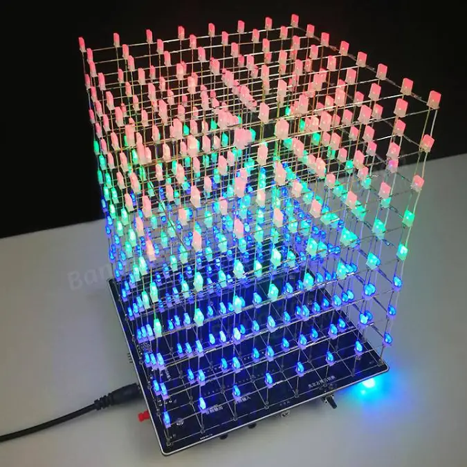
Note: I should have ordered this multicolor-Music LED cube version having three different colors(RGB) in one LED as it looks more appealing.

Hi, I just put one together but am a bit lost on the S1-S3 and K1-K4 pushbuttons..can you help explain these and how to use? Thanks, Leo
I’m in the same boat. The demo software just loops, and even though I went through the painstaking task of translating the Chinese to English, what the C-code says and what the hex-code does are two very different things, and I am baffled
hi greetings one hobby I’ve made this project and i’m confused to program it can you help me🙏🙏🙏