
Last updated on March 18th, 2024 at 05:12 pm
For anyone interested in electronics, learning how to make series and parallel circuits on a breadboard is a fundamental skill. These kinds of connections are very crucial in circuits to join together two or more components.
Before making connections on a breadboard, let’s understand what series and parallel connections are.
Table of Contents
What is a series circuit?
In a series connection, two or more components, such as a resistor and an LED, are connected end-to-end and experience the same current flow. However, the voltage across each component is different, resulting in different voltage drops.
The sum of all the voltage drops across the components is equal to the total voltage from the source, such as a battery. Understanding the concept of voltage drops in a series connection is crucial for building and troubleshooting electronic circuits.

In the image given above, Resistors 1, 2, and 3 are connected to the positive and negative terminals. Current flows from the positive terminal through Resistor R3 to R2 to R1, and finally back to the battery’s negative terminal.
Since the same current flows through all three resistors, they are in series. In a series connection, the circuit’s total resistance is equal to the sum of the individual resistances of the components (R = R1 + R2).
What is a Parallel Circuit?
In a parallel circuit, components are connected side by side, and the voltage across each component is the same. The current between each component is divided.
In a parallel connection, the total current flowing in the circuit is equal to the sum of the current flowing through individual components.

Here in the above diagram, resistors R1, R2, and R3 are connected in parallel, with one end of each resistor connected to the positive terminal of the battery and the other ends connected to the negative terminal of the battery.
Here in this circuit, voltage across each resistor is the same as the voltage of the battery. The current across each component can be found by Ohm’s law V=IR, V is voltage, I is current, and R is the resistance value.
In parallel connection total resistance (R= 1/R1 +1/R2).
Now let’s learn how to make series and parallel connections on a breadboard.
Series circuit on a breadboard
Components Required:
- Resistor- 3 x 10Kohm
- Breadboard wires(Jumper/ solid core/ pre-bent wire)
- Breadboard
- Battery- 9V
To make a series circuit on a breadboard:
Take the resistors and connect them in a manner such that one end of the first resistor is connected to one end of the second resistor, and so on. Follow the steps given below:
Note: Resistors do not have any polarity, so you can connect them in any manner in a circuit.
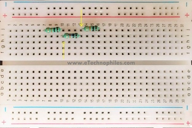
Step 1: Insert the ends of the first resistor into J7 and J10, respectively.
Step 2: To connect the second resistor in series with the first one, insert its one end into the same row i.e, row 10. I have connected its one end into the hole i10. Insert its other end in hole i13.
Step 3: Insert the ends of the last resistor in j13 and j16, respectively. All the resistors are now connected in series on the breadboard.
But how can we say that these are now connected in series? Actually, the individual ends of the resistors are connected to a 5-hole metallic strip(inside the breadboard), as shown below. To know more about its internal connections, read this article.

Step 4: Now connect the positive and negative terminals of the battery to the remaining ends of the first and last resistor respectively(h7 and h16).

Note: Since all the circuits in this article are simple and there are not many components on the breadboard, we have connected the battery’s terminals directly across the components. In normal use cases, always connect the ends of the battery/supply to the power rails.
Be Project ready with these breadboard kits. (Read now)

Verify the series circuit practically
Verifying the series connection of the resistors is very simple. If the sum of the voltage across individual resistors is equal to the total voltage of the battery, then the resistors are connected in series.
The voltage of the battery is: 9.27V (at the time of measurement)
- The voltage across the first resistor is 3.10V, say V1(as shown below)

- The voltage across the second resistor is 3.12V(V2)

- The voltage across the third resistor is 3.04V(V3)

- The voltage across all three resistors is 9.26.
On adding the individual voltage drop across the resistors, we get V1 + V2 + V3 = 3.10 + 3.12 + 3.04 = 9.26 Volts. This is equal to the measured voltage across the circuit. Hence the resistors are indeed in series.
Parallel circuit on a breadboard
Components Required
- Resistor – 3×10 Kohm
- Wires(Jumper/ solid core/ pre-bent wire)
- Breadboard
- Battery-9V
To make a parallel circuit on a breadboard:
The ends of every resistor should be connected together. To achieve this on a breadboard, the ends should be connected to the same node(metallic strip/row). There are two ways to do this. One is simpler, as shown below.
Step 1: Connect one terminal of all the resistors to row 10 and the other terminal to row 13. I have connected one end to – i10, h10, and g10; and the other end to i13, h13, and g13 as shown below.

So that you can learn the breadboard connections better, let’s step up the complexity. The same resistors can be connected in parallel using the second method as shown below.
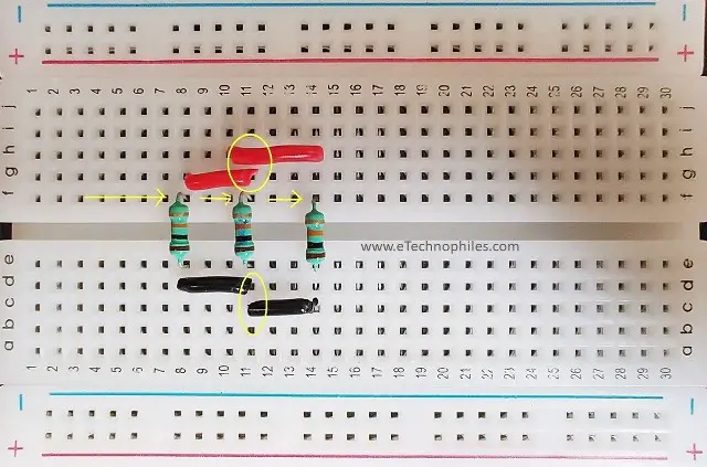
To connect the end terminals of the resistors together, simply use wires to create a connection between different rows.
Step 2: Now connect the positive and negative terminals of the battery to any of the opposite holes across the center divider. (i8 and c8).

Note: All the connections here are made using solid core wires, you can learn more about the different kinds of prototyping wires by referring to our article on breadboard wires.
Verify the parallel circuit practically
If the resistors are connected in parallel, then the voltage across each one of them should be the same.
- The voltage across the first resistor is 9.57 V(see the image given below)

- The voltage across the second and third resistors is also 9.57 V.(The voltage across the third resistor is not shown here)

As you can see, the voltage across each of the resistors is indeed the same, so we have made a successful parallel connection on the breadboard.
FAQs
Is the breadboard parallel or series?
A breadboard isn’t inherently parallel or series; it’s a tool for prototyping circuits. Components can be connected in series or parallel based on circuit design.
What is a breadboard also called?
A breadboard is also commonly referred to as a prototyping board or solderless breadboard.
Why is parallel better than series?
Parallel connections are often preferred due to their ability to provide consistent performance for each component and independent operation if one fails. They can handle higher currents and maintain voltage across components. However, the choice between parallel and series depends on specific circuit requirements and constraints.
love the explanation. ive a physics lab exam after two days and LCR experiment is clear for me now.