Last updated on July 31st, 2025 at 10:18 am
A speed controller circuit uses MOSFETs or IGBTs to control the speed of a DC Motor. A standard motor driver module gives a maximum current of up to 2 Amps. This current is not sufficient to run high power motors. So a separate controller is designed using transistors.
Powerful H bridge DC motor driver

In this project, the speed controller drives a windscreen wiper DC motor. An Arduino Uno board provides the necessary controlling signals to the controller. The duty cycle is varied using the push-buttons provided on the keypad. And the PWM pulse obtained can be seen on the oscilloscope.
The controller is efficient in running, braking, and changing the direction of rotation. The current-carrying capability of the PCB board is high with minimal heat losses.
Components list
- Power MOSFET (IRF3205)
- MOSFET driver (IR2104)
- DC Motor
- Arduino Uno
- Resistors
- Capacitors
- Diodes
- Push-buttons
- Connecting Wires
- PCB Board
Looking to add a transformer to your motor controller PCB? Learn everything you need to know about PCB transformers here.
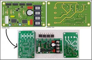
PCB details
The image shows the PCB designed in the software.

And right here is the fabricated PCB.

The designed PCB looks similar to the fabricated PCB. The exposed PCB tracks can carry a high current safely without heating the PCB board.
**To know more about the following project, click on the link below:
–> Powerful H-bridge DC Motor driver
DC motor driver using L293D

The speed controller used here consists of an L293d IC with a custom motor driver made using transistors. This combination is suitable for low and medium power circuits. The controller efficiently drives three motors in forward and reverse directions.
The controller receives the controlling signals from a microcontroller. If the current required by the external load is low, then the circuit allows the operation of L293d alone. For moderate current requirements, both motor drivers serve the purpose.
Components required
- L293d IC
- Transistors
- Resistors
- Capacitors
- LEDs
- PCB board
PCB details
The image here shows PCB designed in software.

And here is the fabricated PCB.

**To know more about the following project, click on the link below:
–> DC Motor driver using L293d
PWM speed controller using 555 timer

This project is simple than the projects discussed above. It allows speed control using NE555 IC. A potentiometer varies the speed of the motor. As the duty cycle increases, the rotation of the motor increases.
The input and output current waveforms are viewed by attaching an oscilloscope to the PCB board. The circuit is compact, simple, and used for low power motors. PWM has advantages over discrete switching in the case of inertial loads like motors. For a smooth output waveform, the switching frequency must be higher.
Components required
- NE555 IC
- Transistors
- Potentiometer
- Diodes
- Capacitors
- Resistors
PCB details
The PCB is simple to design. The fabricated PCB received from PCBWay is shown in the figure below.

On soldering the necessary components, the PCB board looks like this.

Although the PCB board looks compact, it is highly efficient for driving small loads.
**To know more about the following project, click on the link below: