Last updated on April 5th, 2024 at 11:05 am
XLR is an electrical connector mainly used for cabling in audio and video applications. These connectors are also used in lighting control, low-voltage power supplies, etc. XLR connector was discovered by James H Cannon (the founder of Cannon Electric in Los Angeles). Hence they are also known as Cannon Connectors.
XLR connections fall under the dimension standard IEC 61076-2-103.
XLR connector was initially known as the X connector. Later, the latch (L) and a synthetic rubber compound (R) were added to this connector, the name became XLR connector.

XLR pinout
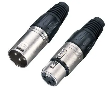
The XLR connectors are circular. The most common XLR is the 3-pin connector, but there are other connector variants whose number of pins ranges from two to seven. All these variants have both male and female versions.
The pins of the XLR connector are arranged circularly as shown in the figure. Let us see the pinouts of the relevant types in XLR connectors.
Note: The article shows the pinout of the male version of the connectors. The pin arrangement in the female version is the exact mirror replicate of the male version.
XLR3 pinout

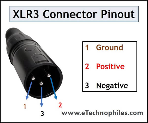
The number 3 here shows that it is a 3-pin XLR connector. It is the most common industry standard for balanced audio signals. We can see this XLR port in the majority of professional microphones. They are also used in electric wheelchairs and scooters. The pinout diagram of XLR3 is given below.
| Pin number | Description |
| 1 | Ground |
| 2 | Positive |
| 3 | Negative |
Note: A major advantage of the XLR connector can be understood according to this pinout. As we can see, pin 1 is the ground reference. Pin 2 and 3 are for the same signal with opposite polarity, i.e., Pin 2 carries the exact signal, and Pin 3 carries the signal in its opposite polarity. This method cancels out any electrical interference carried in the line.
XLR4 pinout

The XLR connector with 4 pins is mostly used in intercom headsets. Among the four pins, two pins carry the headphone signals and the other two pins carry the microphone signals. The other popular applications are in DC power connections and professional cameras used in the film industry.
| Pin Number | Description |
| 1 | Left Channel + |
| 2 | Left Channel – |
| 3 | Right Channel + |
| 4 | Right Channel – |
XLR5 pinout

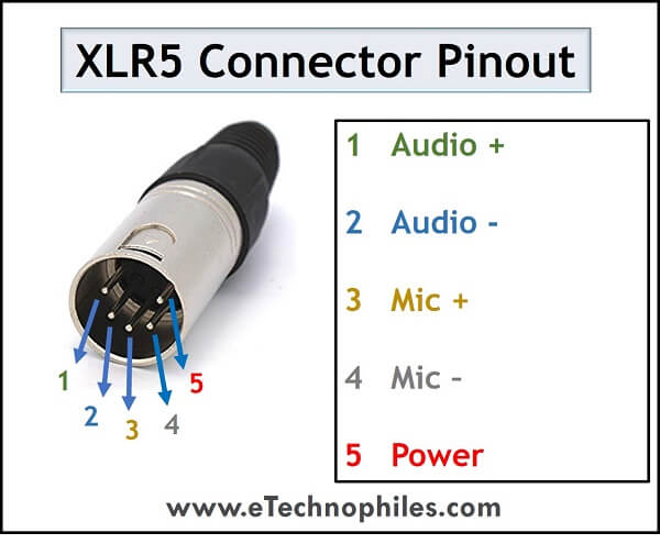
XLR5 is the standard connector for DMX512 digital lighting control. It is used to carry dual-element audio signals like stereo signals. The XLR connector with 5 pins is almost similar to that of XLR4 except that it has an additional one pin for power.
| Pin Number | Description |
| 1 | Audio+ |
| 2 | Audio- |
| 3 | Mic+ |
| 4 | Mic- |
| 5 | Power |
XLR6 pinout

XLR6 comes in two types; “Switchcraft Type” and “Neutrik Type”. Switchcraft is a symmetrical connector and the other one is asymmetrical. The common uses of XLR6 are stage lighting control, intercom systems, professional stereo headsets with balanced microphones, etc.
| Pin Number | Description |
| 1 | Data+ |
| 2 | Data- |
| 3 | Data+ |
| 4 | Data- |
| 5 | Ground |
| 6 | Power(+12V) |
Hot plugging
Hot plugging means inserting or removing a component from the system while the system is in use. In XLR3 connectors, the ground pin of male and female versions makes the first contact during insertion. Also, it disconnects the last during removal.
This ensures that no unnecessary noise enters the system while making the connection. Hence XLR connector gives better performance while using them in a live session.
Advantages of XLR connectors
- They’re capable of delivering the 48-volt phantom power that’s needed to power condenser microphones.
- Balanced wiring cancels out interference that’s being picked up along the way.
- They have a little latch on the connector to prevent accidental unplugging.
FAQs
What is XLR male and female?
XLR connectors come in two genders, male and female, differentiated by their structure and function:
XLR Male: This connector has three pins enclosed within a protective metal casing, commonly used in microphone cables as the output for audio signals.
XLR Female: Featuring a socket with three holes to accept the pins of the male connector, this type is typically found on mixers, amplifiers, and other audio equipment, serving as the input for audio signals.
Is XLR better than Jack?
It depends on the specific needs and application. XLR connectors are often preferred for professional audio due to their balanced design, while Jack connectors are more common in consumer electronics and instruments.
What is 7-pin XLR used for?
A 7-pin XLR connector is commonly used for specialized audio applications requiring additional features like remote control, powering accessories, or multi-channel audio transmission.
