Last updated on March 16th, 2024 at 01:35 pm
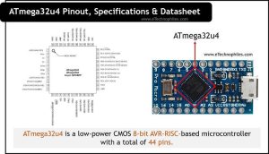
ATmega32u4 is a low-power CMOS 8-bit AVR-RISC-based microcontroller. It has 32KB of programmable flash memory and 2.5KB of SRAM.
ATmega32U4 has 44 total pins, of which 6 are analog input pins, and 14 are digital pins. Out of these 14 digital pins, seven can be used as PWM pins, 4 SPI pins, 1 I2C port, and 1 UART port (2 pins).


ATmega32U4 is useful in projects that have multiple devices connected to it and require many VCC and ground pins.
Table of Contents
Specifications
- ATmega32U4 is an AVR-RISC-based microcontroller fabricated as a DIP IC or SMD package with a total of 44 pins.
- These 44 pins consist of 6 analog pins, 2 VCC pins, 4 GND pins, and 14 digital pins. 7 out of 14 digital pins can be used as PWM pins.
- It has 1 MOSI and 1 MISO pin, 1 HWB pin that gives the user access to the bootloader and can be used as normal GPIO pins. ATmega32U4 has 1 UART port, 4 SPI peripheral along with 1 I2C pin.
- ATmega32u4 has 32 KB of programmable flash memory 2.5 KB of SRAM, and 1 KB of EEPROM.
- This microcontroller accepts voltage anywhere between 2.7 – 5.5 volts and has an operating temperature range of -40 to 85 C.
Architecture

The ATmega32U4 follows the AVR-RISC (Harvard architecture) and the CPU core ensures the correct execution of instructions. It has separate buses for programs and data. The microcontroller has two main memory spaces, the Data Memory and the Program Memory space. In addition, it also has an EEPROM Memory for data storage. Memory space map in this architecture is linear and regular.
The ALU of ATmega32U4 operates in direct connection with all 32 general-purpose working registers and multiple clocks and can provide different sources to be operated. All the clocks need not be active at the same time.
The design and architecture of the microcontroller provide 1 MIPS per MHz of the CPU speed. The designers can optimize power consumption and processing speed to get the optimum working of the circuitry.
ATmega32u4 Pinout

ATmega32U4 has a total of 44 pins, of which 6 are analog input, and 14 are digital pins. Out of these 14 digital pins 7 can be used as PWM pins, 4 SPI pins, 1 I2C peripheral, and 1 UART port (2Pins). The complete pinout is given in the table below.
| Pin Number | Name | Description |
|---|---|---|
| 14,34 | VCC | Supply pins |
| 15, 23, 35, 43 | GND | Ground pins |
| 42 | AREF | Reference supply for ADC |
| 24, 44 | AVCC | Supply pins for analog Peripherals |
| 16, 17 | XATL | Crystal oscillators pins |
| 13 | RESET | Reset pins |
| 33 | PE2 | HWB |
| 10, 11 | PB2,PB3 | MISO, MOSI |
| 4 | D+ | RD+ |
| 3 | D- | RD- |
| 8 | PB0 | RXLED |
| 22 | PD5 | TXLED |
| 5 | UGnd | UGND |
| 2 | UVcc | +5V |
| 6 | Ucap | UCAP |
| 7 | VUSB | Vbus |
| 20 | PD2 | Digital Pin (RX) |
| 21 | PD3 | Digital Pin (TX) |
| 18 | PD0 | Digital Pin (PWM, SCL) |
| 19 | PD1 | Digital Pin (SDA) |
| 1, 25, 26, 28 | PE6, PD4, PD6, PB4 | Digital Pins |
| 12, 27, 29-32 | PB7, PD7, PB5, PB6, PB6, PB7 | Digital Pins (PWM) |
| 36-41 | PF7-PF0 | Analog Pins |
Read also: ATmega328p Pinout, datasheet, and specifications
Pin Description
Vcc: ATmega32U4 has 2 VCC pins: pin 14 and 34. These pins can give an output voltage in the range of 4.5-5.5 volts.
GND: ATmega32U4 has 4 ground pins (15,23,35,43). Many microcontrollers offer multiple ground pins because:
- Multiple ground reduces overall inductance and internal resistance which helps in Heat dissipation, lowering current density to avoid damage.
- Makes the job of the designers easy to connect multiple devices
AVCC: AVCC is the input voltage supply pin for ADC channels. If the ADC is not being used then it should be externally connected to VCC. If the ADC is used, then it should be connected to VCC through a low-pass filter.
AREF: This is the analog reference input pin for the ADC
XATL: These pins are for the inverting oscillator amplifier and also for the input of internal clock operation.
HWB: HWB is a special pin that allows the user to execute the bootloader. During normal operation, it acts as a normal GPIO pin.
D-/D+: These pins are Data Upstream Positive/Negative USB full-speed or low-speed ports. These should be connected to USB D-/D+ ports respectively with a 22-ohm resistor.
UGND/UVCC: These are the USB pads for Input supply voltage.
UCAP: It is a USB pad for the Internal Regulator Output supply voltage that should be connected to an external capacitor.
Datasheet
Given below is the datasheet of ATmega32u4 by Atmel. You can download it from here.

Which board uses an ATmega32u4 microcontroller?
There are a few development boards that use ATmega32u4 microcontroller. These are:
- Arduino Pro Micro
- Arduino Leonardo R3
- Arduino Leonardo mini
ATmega32U4 vs ATmega328P
Although both ATmega32U4 and ATmega328P are similar, there are a few differences between them. The ATmega32U4 provides more GND and VCC pins along with more SPI peripherals and access to the bootloader programs.