Last updated on March 16th, 2024 at 01:32 pm
The ATmega2560 was specially designed for complex circuitry and more storage, most of the electronics projects can be performed on other microcontrollers which makes this uncommon, but few projects can be solely done by ATmega2560 as other microcontrollers lack in terms of pins, storage, and performance.
The ATmega2560 is majorly seen in the Arduino Mega development board. This board is really useful in robotics projects that require a large number of GPIO pins.


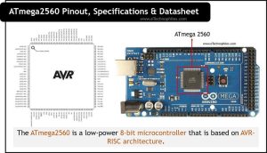
The ATmega2560 is a low-power 8-bit microcontroller that is based on AVR-RISC architecture. It can execute powerful instructions and its clock frequency is 16MHz. This microcontroller has 8KB SRAM, 4 KB EEPROM, and 256KB of programable flash memory with read-write capabilities. 8 KB out of 256 KB flash memory is used by the bootloader.
Table of Contents
Specifications of ATmega2560
The ATmega 2560 operates in a voltage range of 7-12V. This microcontroller has 8KB SRAM, 4 KB EEPROM, and 256KB of programable flash memory. Other specifications are listed in the table below.
| Name | Value |
|---|---|
| Program memory | 256KB (flash) |
| RAM | 8KB SRAM |
| Communication peripherals | 4-UART, 5-SPI, 1-I2C |
| Temperature range | -40 to 85 C |
| Operating Voltage Range | 7-12 volts (recommended) |
| Pin Count | 100 |
| Digital Pins | 54 |
| Analog Pins | 16 |
| PWM peripherals | 15 Pins |
| CPU | 16 MIPS/DMIPS |
| Timer | 2 x 8-bit, 4 x 16-bit |
Architecture

The AVR core of ATmega2560 combines a rich set of instructions with 32 general-purpose working registers. All 32 registers are directly connected to the Arithmetic Logic Unit (ALU). The resulting architecture is more code efficient and ten times faster than conventional CISC microcontrollers.
CPU
To maximize performance, the Atmega2560 uses an AVR-RISC (Harvard architecture) – with separate memories and buses for program and data. While one instruction is being executed, the next instruction is pre-fetched from the program memory. This concept enables instructions to be executed in every clock cycle. The program memory is In-System Reprogrammable Flash memory
ALU
The ALU supports arithmetic and logic operations between registers or between a constant and a register. Single register operations can also be executed in the ALU.
Memory
ATmega2560 has two main memory spaces: the Data Memory and the Program Memory. In addition, ATmega2560 contains 256KB In-System Reprogrammable Flash memory for program storage.
For software security, the Flash Program memory space is divided into two sections, the Boot Program section and the Application Program section.
Clock
The ATmega2560 has multiple clocks, i.e., CPU clock, I/O clock, Flash clock, ADC clock, and Asynchronous clock. All the clocks of Atmega2560 need not be active at a given time. In order to reduce power consumption, the clocks modules not being used can be halted by using different sleep modes.
Register
The ATmega2560 has 32 × 8-bit general-purpose working registers with a single clock cycle access time. Six of the 32 registers can be used as three 16-bit indirect address register pointers for Data Space addressing, enabling efficient address calculations.
Communication Peripherals
The ATmega2560 offers 4 ports of UART communication (TX-RX), 5 SPI peripherals, and one I2C peripheral.
Operating parameters
The input voltage range of the ATmega2560 is 2.7V – 5.5V. The output current from the input-output pins is near around 40mA.
Read also: ATmega328p Pinout, datasheet, and specifications
ATmega2560 Pinout

There are a total of 100 pins on ATmega2560, of which 16 are analog input pins and 54 digital input/output pins. Out of 54 digital pins, 15 can be used as PWM pins. It also has 4 UART ports (8 pins), 5 SPI peripherals, and 1 I2C port. The complete pinout is given in the table below.
| Pin Number | Name | Description |
|---|---|---|
| 10, 31, 61, 80 | VCC | Supply Pins |
| 11, 32, 62, 81, 99 | GND | Ground pins |
| 98 | AREFF | Reference supply for ADC |
| 100 | AVCC | Supply pin for analog peripherals |
| 33, 34 | XATL | Crystal oscillators pins |
| 30 | RESET | Reset pin |
| 2, 3 | PE0, PE1 | Digital pin (TX0, RX0) |
| 46-47 | PD2,PD3 | Digital Pins (TX1, RX1) |
| 12,13 | PH0,PH1 | Digital Pin (TX2, RX2) |
| 63, 64 | PJ0, PJ1 | Digital Pins (TX3, RX3) |
| 5-7 | PE3-PE5 | Digital Pin (PWM) |
| 15-18, 24-26 | PH0-PH6, PB4-PB7 | Digital Pin (PWM) |
| 38-40 | PL3-PL5 | Digital Pin (PWM) |
| 19, 20 | PB0, PB1 | Digital Pin (SS, SCK) |
| 35-37 | PL0-PL2 | Digital Pin |
| 47-60 | PC0-PC7 | Digital Pin |
| 70-78 | PA7-PA0 | Digital Pins |
| 4,8,9,14 | PE2,PE6,PE7,PH2 | Digital Pin |
| 28-29, 51-52, 70, 1 | PG3-PG4, PG0-PG1, PG2, PG5 | Digital Pins |
| 82-97 | PF7-PF0, PK7-PK0 | Analog Pins |
Datasheet
Given below is the datasheet of ATmega2560 by Atmel. You can download it from here.

Why ATmega2560 is better?
ATmega2560 is preferably used when we need more GPIO pins, flash memory, or faster executions. ATmega2560 provides comparatively more IO pins than other microcontrollers of this series available in the market. ATmega2560 offers 8KB of SRAM and 256KB of flash memory which is more as compared to other microcontrollers.
Which boards use ATmega2560?
ATmega2560 microcontroller is present in many development boards, among which the most common is Arduino mega. Some of the boards that use ATmega2560 microcontroller are:
- Arduino Mega2560
- Seeeduino Mega
- Mega Wi-Fi R3 Atmega2560