Last updated on March 26th, 2024 at 05:54 pm
The HC-06 is a class-2 slave Bluetooth module designed to enable wireless serial communication between microcontrollers (like Arduino) and other Bluetooth-enabled devices. HC-06 pinout and specifications are given below.
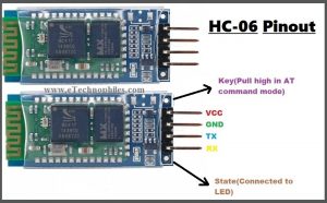
HC-06 pinout with description
HC06 is a slave Bluetooth device that offers serial communication (UART). Hence, a master is required to establish a successful wireless interface. The module has only communication and power pins. Please note that some HC-06 modules may have 6 pins. But only 4 of them are used.

| PIN NO. | Pin Name | Description |
| 1. | VCC | Used to power the module. Connect it to a 3.3V pin of the microcontroller. |
| 2. | GND | Connect this pin to the common ground of the circuit. |
| 3. | TXD | Connect this pin with the RXD pin of the Microcontroller. This pin transmits Serial data (wireless signals received by the Bluetooth module are converted by module and transmitted out serially on this pin) |
| 4. | RXD | Connect this pin to the TXD pin of the Microcontroller. The HC-05 Bluetooth module receives the data from this pin and then transmits it wirelessly. |
HC-06 specifications
- Bluetooth protocol: Bluetooth 2.0+ EDR standard
- USB protocol: USB v1.1/2.0
- Operating frequency: 2.4GHz ISM frequency band
- Modulation mode: Gauss Frequency Shift Keying
- Transmit power: ≤ 4dBm
- Sensitivity: ≤-84dBm at 0.1% Bit Error Rate
- Transmission speed: 2.1Mbps(Max)/160 kbps(Asynchronous); 1Mbps/1Mbps(Synchronous)
- Safety feature: Authentication and encryption
- Supported configuration: Bluetooth serial port (major and minor)
- Supply Voltage: +3.3 VDC 50mA
- Operating temperature: -20 to 55℃
- Size: 36.5*16mm
- Weight: 4g
**HC-05 Pinout and specifications
HC-06 bluetooth module datasheet


Download the full datasheet from this link: HC-06 Datasheet
Introduction to HC-06 bluetooth module
The HC-06 is a class-2 slave Bluetooth module. It is designed to enable wireless serial communication between microcontrollers (like Arduino) and other Bluetooth-enabled devices.

All data received through the serial input is immediately transmitted wirelessly by the module. And when the module receives some wireless data from the master device (like a smartphone ), this data is sent out through the serial interface.
The HC-06 operating voltage is between 3.3V to 5V. However, the tolerance level of RXD pin is 3.3V and not 5V. Hence, a Logic Level Converter is recommended to convert the 5v input to 3.3V.
HC-05 Breakout board pinout

| PIN Name | PIN | Pad type | Description |
| GND | 13 21 22 | VSS | Ground pot |
| 1V8 | 14 | VDD | Integrated 1.8V (+) supply with an on-chip linear regulator output within the range of 1.7V-1.9V |
| VCC | 12 | 3.3V | |
| AIO0 | 9 | Bi-Directional | Programmable input/output line |
| AIO1 | 10 | Bi-Directional | Programmable input/output line |
| PIO0 | 23 | Bi-Directional RX EN | Programmable input/output line, control output for LNA(if fitted) |
| PIO1 | 24 | Bi-Directional TX EN | Programmable input/output line, control output for PA(if fitted) |
| PIO2 | 25 | Bi-Directional | Programmable input/output line |
| PIO3 | 26 | Bi-Directional | Programmable input/output line |
| PIO4 | 27 | Bi-Directional | Programmable input/output line |
| PIO5 | 28 | Bi-Directional | Programmable input/output line |
| PIO6 | 29 | Bi-Directional | Programmable input/output line CLK_REQ |
| PIO7 | 30 | Bi-Directional | Programmable input/output line CLK_OUT |
| PIO8 | 31 | Bi-Directional | Programmable input/output line |
| PIO9 | 32 | Bi-Directional | Programmable input/output line |
| PIO10 | 33 | Bi-Directional | Programmable input/output line |
| PIO11 | 34 | Bi-Directional | Programmable input/output line |
| RESET | 11 | CMOS (Complementary-metal-oxide-semiconductor) Input with weak internal pull-down | |
| UART_RTS | 4 | CMOS (Complementary metal-oxide-semiconductor) output, tri-stable with weak internal pull-up | UART request to send, active low |
| UART_CTS | 3 | CMOS input with weak internal pull-down | UART clear to send, active low |
| UART_RX | 2 | CMOS (Complementary metal-oxide-semiconductor) input with weak internal pull-down UART Data input | |
| UART_TX | 1 | CMOS output, Tri-stable with weak internal pull-up | UART Data output |
| SPI_MOSI | 17 | CMOS input with weak internal pull-down | Serial peripheral interface data input |
| SPI_CSB | 16 | CMOS input with weak internal pull-up | The chip select for the serial peripheral interface, active zero |
| SPI_CLK | 19 | CMOS input with weak internal pull-down | The serial peripheral interface clock |
| SPI_MISO | 18 | CMOS input with weak internal pull-down | Serial peripheral interface data Output |
| USB_- | 15 | Bi-Directional | |
| USB_+ | 20 | Bi-Directional | |
| 1.8V | 14 | 1.8V | external power supply input |
| PCM_CLK | 5 | Bi-Directional | |
| PCM_OUT | 6 | CMOS output | |
| PCM_IN | 7 | CMOS Input | |
| PCM_SYNC | 8 | Bi-Directional |
HC-06 Arduino connections

Image Source: Hackster
In this project, an LED is controlled using a smartphone via Bluetooth. HC-06 Bluetooth module receives the commands from the smartphone via Bluetooth signals. These commands are then processed by the Arduino UNO to control the LED connected to one of its digital I/O pins.
**For full project details, click here: Control LED with Bluetooth
Applications
- HC-06 is a class Bluetooth module, that can be used in different electronic devices such as a mobile, laptop, personal computer, etc.
- It can also be used in different industrial projects for sending and receiving data.
- Different robotics projects.
- Mobile phone wireless accessories.
Read a similar article on HC-05 Bluetooth Module:
HC-05 pinout, specifications, datasheet, and Arduino Connections.