Last updated on March 1st, 2024 at 12:28 pm
Continuity Tester is a simple electronics tool that indicates the continuity of a circuit when that circuit is connected between the connecting probes of Continuity Tester Circuit. This Continuity Tester circuit can be easily made by using a simple 555 timer.
IC 555 timer is one of the most popular ICs among electronic hobbyists and engineers, even after more than 46 years of its invention.
Due to its wide range of applications in electronics, many projects can be easily made using this IC. 555 timer is used for many purposes in the electronic industry as a monostable and astable multivibrator. 555 timer can also be used as a continuity tester in its monostable mode or single shot mode.
Watch the video tutorial below:
Components required
To make this continuity tester circuit using a 555 timer, you need the following components:
- 555 timer Ic
- Buzzer
- Capacitors 100uf and .01uf
- 9-volt battery
- Resistors 4.7k and 47k
- Connecting probes
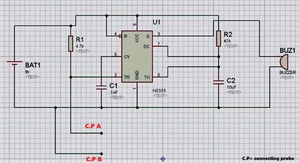
Circuit diagram

*C.P = Connecting Probe
| Pin no. | Pin Name | Connection |
|---|---|---|
| 1 | GND | To -ve terminal of the battery |
| 2 | TRIGGER | Between one C.P and 4.7k resistor |
| 3 | OUTPUT | To Buzzer |
| 4 | RESET | To +ve terminal of a battery |
| 5 | CONTROL | To .1uf capacitor |
| 6 | THRESHOLD | Between 47 k resistor & 10 uf capacitor |
| 7 | DISCHARGE | Between 47 k resistor & 10 uf capacitor |
| 8 | VCC | To +ve terminal of battery |
Working of continuity tester circuit
Two important points to consider in IC ne555 timer:
A. Output or Pin 3 of the 555 timers will be 1(HIGH) only when the voltage at pin 2 or trigger pin is less than 1/3v of the applied voltage at the Vcc pin of 555.
Since the battery is 9 volts, hence :
1/3 of 9 = 3
B. Capacitor (100 uf) discharges through discharge pin (7th) to ground as soon as the voltage at pin 6 or threshold pin of 555 timers is greater than 2/3v of the applied voltage at the 8th pin or Vcc pin.
2/3 of 9 = 6
Connect ends of a wire or circuit (whose continuity you want to check) to respective C.P:
Case 1: When there is a break in a circuit.
In this case, all voltage drops across an open circuit(since there is a break) as it acts as an infinite resistor. Due to this, voltage at pin 2 or trigger pin is greater than 1/3 of 9v, causing a reset of flip-flop inside the 555 timer and thus zero volt as output. Now since the output pin is directly connected to the buzzer, it produces no sound.
Case 2: When there is no break in a circuit.
In this case, the resistance between pin2 and GND is 0, so all voltage drops across the 4.7k resistor. Due to this, voltage at pin 2 or trigger pin is less than 1/3 of 9v, causing a set of flip-flops inside the 555 timer and thus one as output. Now since the output pin is directly connected to the buzzer, it produces a beep sound.


If I put 1M ohm resistor across probes, will the buzzer sound comes?