Last updated on March 22nd, 2024 at 01:16 pm
Voltmeters are required in almost every sector of the electrical and electronics industry. And since Digital multimeters are easily available in the market, buying one is no big issue as it can measure all electrical quantities.
But the real problem arises when one wants to make an analog voltmeter because making one is not easy. Whereas a digital voltmeter can be made easily using a microcontroller (we will use Arduino for this purpose). Arduino will take step-down AC voltage as input and display the real AC voltage on the serial monitor. You can also use an LCD to display the voltage.
This circuit can measure AC voltage as high as 311 volts (r.m.s). It also protects the microcontroller if this AC voltage exceeds 311 volts.
If you prefer video tutorials instead, then watch this video:
Table of Contents
Components
1. One 12 – 0 – 12 transformer

2. Resistor 10k, 4.7k.


3. 1N4007 diode

4. 1uf capacitor

5. Zener diode(5V)

6. Arduino UNO
7. Connecting wires
Circuit diagram
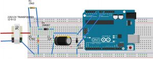
Below is the circuit diagram of the project:

The high voltage side of the transformer should be connected to the direct AC supply, whereas the low voltage side(side and middle wire) is connected to the voltage divider circuit.
The output from the 4.7 k resistor is connected to the diode which rectifies the step-down AC voltage and gives it to the 1UF capacitor which further removes any ripples present. This capacitor charges and provides an input voltage to the A0 pin of Arduino.
Note: Arduino cannot take negative voltage value as input since the negative voltage can damage Arduino. Hence, the input AC voltage must be rectified first. Thus, a diode is used to remove the negative voltage rail. After that, one uF capacitor removes the ripples present and thus provides the smooth voltage value to Arduino.
The Zener diode is used to protect Arduino from damage if the voltage across the capacitor exceeds 5v. When this happens, the Zener diode breaks down, and thus, all current flows through the Zener to the ground, thereby ensuring the safety of the Arduino.
Program
int x;
float y;

void setup()
{
 pinMode(A0, INPUT);
 Serial.begin(9600);
}

void loop()
{
  x = analogRead(A0);
  y = (x * .304177);
  Serial.print("   analog input  ");
  Serial.print(x);
  Serial.print("   ac voltage  ");
  Serial.print(y);
}
Code explanation
- Variable x
X is the input analog value received (voltage) from pin A0 i.e.,
x = pinMode (A0,INPUT) ; // set pin A0 as input pin- Variable y
The task of this variable is most important in the whole program i.e., to convert the input analog value into the actual AC voltage from mains. As in the code:
y= (m*.304177) ; // convert into ac voltagex or actual analog value is multiplied by .304177 because of the following reason:
This exact circuit is simulated in Proteus and the maximum voltage is found out by hit and trial method:

So, by simulating the circuit, we observed that when input a.c voltage is 311 volts, 5 v or 1023 analog value is obtained at pin A0. This voltage is the maximum value that this circuit can measure. Above this voltage, the Zener diode will break down. Hence, 311-volt mains supply corresponds to 1023 analog value.
So, any random analog value obtained is equal to (311/1023)*x ac volts, where x is the obtained analog value.
Hence, we arrive at this formula:
y=(311/1023)x volts or y=(x.304177)
Working of digital voltmeter circuit
Step 1: Transformer steps down the input AC voltage.
Step 2: The voltage divider circuit ensures a voltage less than 5 v across the 4.7k resistor and hence maximum input a.c volts as already seen in the simulation must be 311 r.m.s volts.
Step 3: Arduino receives this voltage as an analog value from pin A0 and converts this value into the actual input a.c voltage by the formula:
y=(x*.304177)
Step 4: This value is printed on the serial monitor; thus, we get the required value of input a.c voltage.


Note – Watch the video given at the beginning to see this code in action.
Printing required values on the screen
Two values are printed on the screen or serial monitor of Arduino IDE, as shown in the picture
Analog input value received by analog pin A0 as specified in the code:
Serial.print(” analog input “) ; // this command specify name on top of the values to be printed which is “ analog input”
Serial.print(x);// this simply prints the input analog value
Serial.print("   analog input  ") ; // this command specify name on top of the values to be printed which is “ analog input”

Serial.print(x);// this simply prints the input analog value
Actual value of AC voltage from mains as specified in the code:
Serial.print("   ac voltage  ") ; // this command specify  name on top of the values to be printed which is “ ac voltage”

Serial.print(y) ;  // this simply prints the ac voltage value
Hi my name is jatin patel I like the method that you did,But I wanted to know that how much 12-0-12 ampr required for it?
Do you want to know the current rating of 12-0-12 transformer?
1 Amp is fine.
I am only getting 311 and 1023 value what might go wrong