
If you’re just getting started with ESP32 or Arduino, you’ve probably seen circuits filled with resistors, capacitors, transistors, LEDs, and other electronic components. At first, they may seem confusing, but each one has a specific purpose. Once you understand what these components do, building and troubleshooting circuits becomes much easier.
In this guide, we’ll look at some of the most important electronic components every beginner should know before diving deeper into microcontroller projects. Instead of memorizing definitions, we’ll understand how each component works through practical examples similar to the ones you’ll encounter in real ESP32 and Arduino projects.
1. Resistor
If you’ve ever searched for an ESP32 or Arduino LED blink project, you’ve almost certainly seen a resistor connected in series with an LED. It’s one of the most common components you’ll find in beginner circuits. But why is it there?
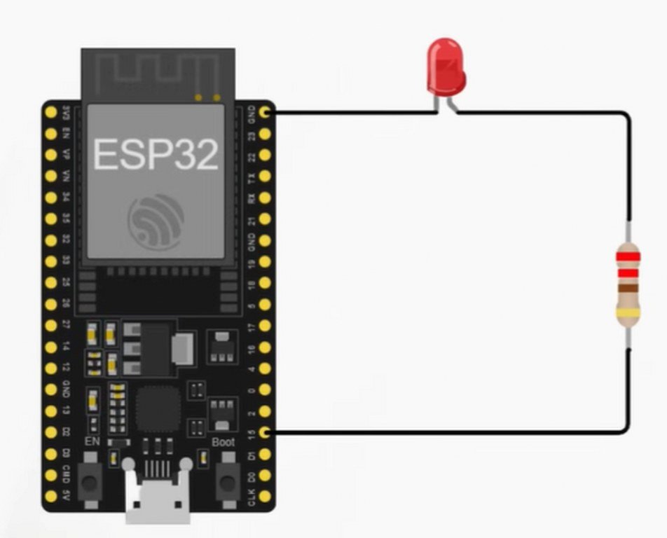
Consider a simple LED blinking circuit connected to an ESP32 GPIO pin. With a resistor in series, the LED lights up normally while only a small amount of current flows through the circuit. Remove that resistor, however, and the LED immediately becomes much brighter because the current increases significantly.
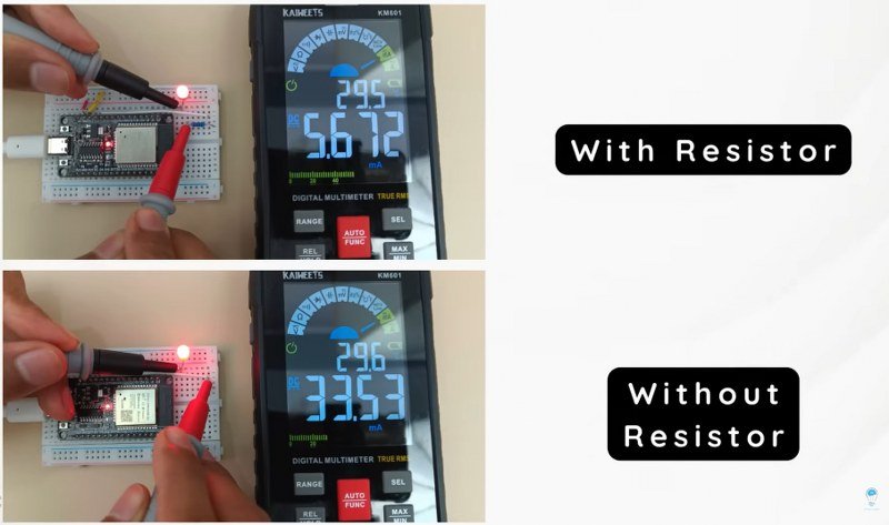
This demonstrates the resistor’s primary job in this circuit: limiting current. By restricting the amount of current flowing through both the LED and the ESP32’s GPIO pin, the resistor protects them from damage.
Why is this important?
Every GPIO pin on an ESP32 or Arduino is designed to deliver only a limited amount of current. Exceeding that limit can permanently damage the GPIO pin, and in extreme cases, even the microcontroller itself. That’s why you’ll almost always find a resistor connected in series with an LED in electronics projects.
Key Takeaway: A resistor in series with an LED doesn’t make the LED work—it makes sure the LED and the microcontroller operate safely.
Are All LED Resistors the Same?
If resistors are so important, why do different tutorials recommend values such as 100 Ω, 220 Ω, or 330 Ω?
The answer depends on several factors, including the supply voltage, the LED’s forward voltage, and the amount of current you want through the LED. We’ll cover how to calculate the correct resistor value in the LED section later in this guide.
Resistors don’t just limit current
Many beginners assume that a resistor’s only purpose is to reduce current, but that’s not always true.
Take a push-button circuit connected to an ESP32. One button turns an LED on, while another turns it off. If you remove the resistors connected to the input pins, something strange happens—the ESP32 starts detecting random button presses even when no button is being touched.
This happens because the GPIO input is now floating. In other words, the pin isn’t connected to either a HIGH or LOW voltage, allowing it to pick up electrical noise from the surrounding environment. As a result, the ESP32 randomly interprets the input as either HIGH or LOW.
Pull-Up and Pull-Down Resistors
To prevent floating inputs, resistors are used to keep GPIO pins in a known state.
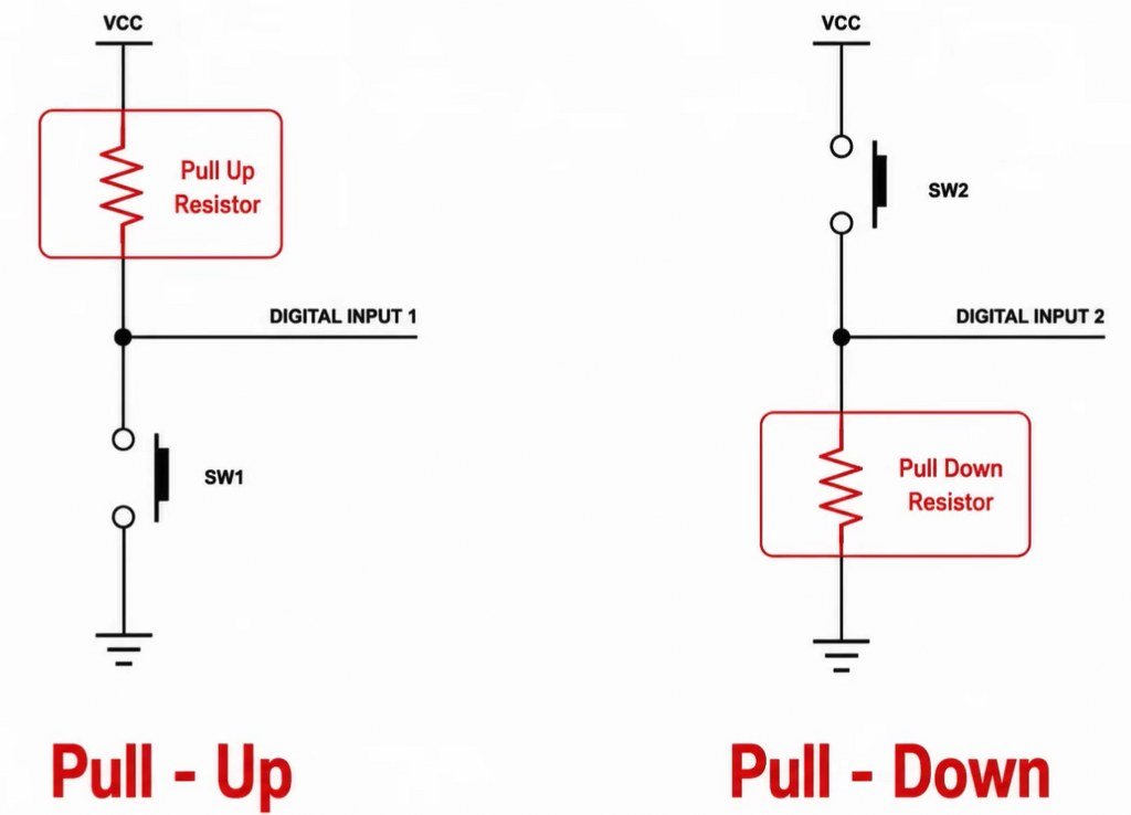
When a resistor connects the input pin to the supply voltage (3.3 V or 5 V), it keeps the pin at a logical HIGH whenever the button isn’t pressed. This configuration is called a pull-up resistor.
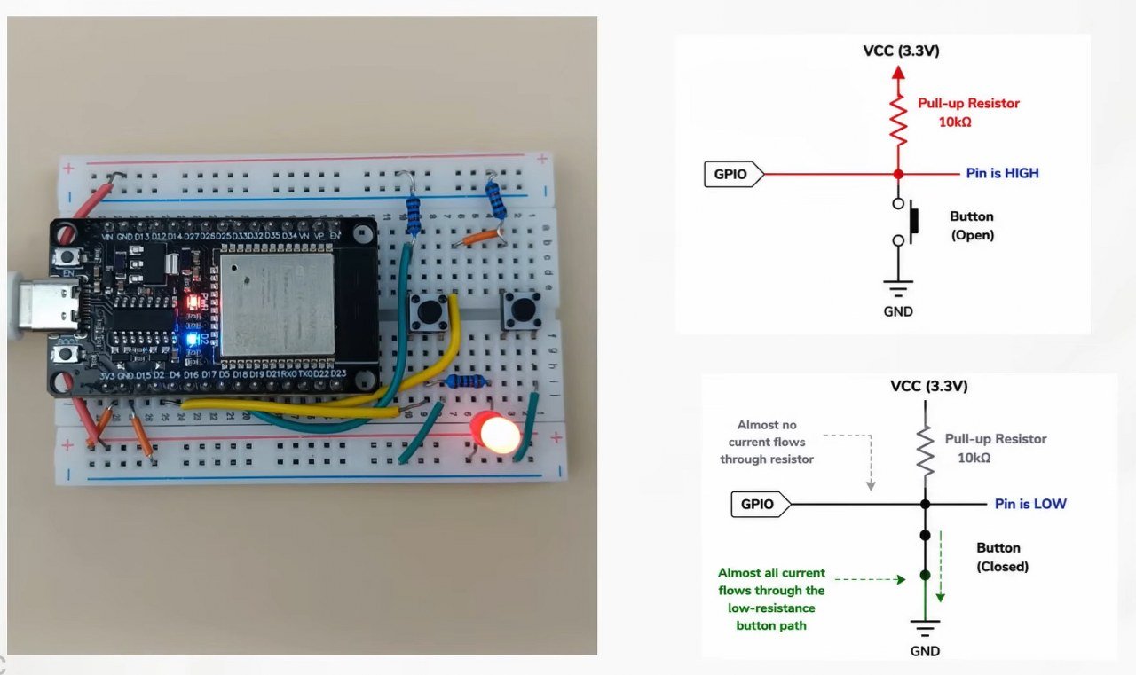
Pressing the button connects the pin directly to ground, causing it to read LOW reliably.
The opposite arrangement is known as a pull-down resistor, where the resistor connects the input pin to ground. In this case, the input normally stays LOW until the button is pressed.
Why Are Pull-Up Resistors Usually 10 kΩ?
Unlike LEDs or motors, GPIO input pins draw almost no current. They only need a stable voltage level to detect whether the input is HIGH or LOW.
That’s why pull-up and pull-down resistors are typically around 10 kΩ. A high resistance is sufficient to keep the input stable while wasting very little power.
When the button is pressed, the direct connection through the switch provides a much lower resistance path than the resistor, ensuring the GPIO pin immediately detects the correct logic level.
2. LED (Light Emitting Diode)
In the previous section, we discussed why an LED circuit always needs a resistor. But that raises another question: how do you choose the correct resistor value? Before answering that, it’s important to understand how an LED works.
What Is an LED?
An LED (Light Emitting Diode) is a semiconductor device that emits light when current flows through it. Unlike an ordinary resistor, an LED is polarized, meaning it only allows current to flow in one direction.
If you connect it the right way, it lights up. Reverse the polarity, and it simply won’t work.
Fortunately, identifying the terminals is easy:
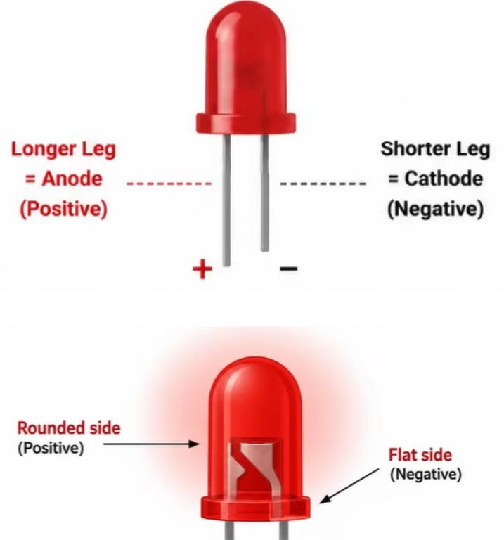
- Longer lead: Anode (+)
- Shorter lead: Cathode (-)
If the leads have been trimmed, look closely at the LED body. The flat edge indicates the cathode (negative terminal).
Different LEDs Have Different Forward Voltages
Although LEDs may look similar, they don’t all operate at the same voltage.
For example:
| LED Color | Typical Forward Voltage |
|---|---|
| Red | ~1.9 V |
| Green | ~2.0 V |
| Blue | ~3.0 V |
| White | ~3.0 V |
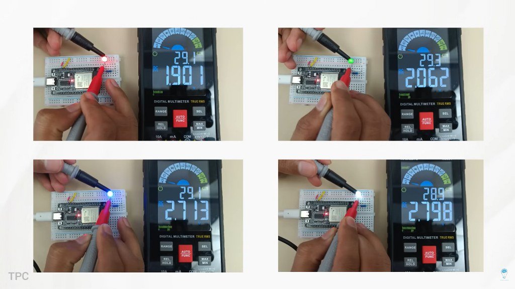
This voltage is known as the forward voltage or forward voltage drop. It’s the amount of voltage the LED consumes while operating normally.
Because different LEDs have different forward voltages, replacing a red LED with a blue one while using the same resistor can change the brightness of the circuit.
Why Does an LED Need a Resistor?
Earlier, we learned that a resistor protects the ESP32’s GPIO pin by limiting current. But the resistor also protects the LED itself.
To understand why, imagine connecting an LED directly across a battery without any resistor.
For a brief moment, the LED becomes extremely bright before permanently burning out.
That’s because LEDs have a maximum current rating. Most standard indicator LEDs are designed to operate at approximately 10–20 mA. If significantly more current flows through them, they heat up rapidly and fail.
So, a resistor serves two important purposes:
- It protects the microcontroller’s GPIO pin.
- It protects the LED from excessive current.
How to Calculate the Correct LED Resistor
Now we have everything needed to calculate an appropriate resistor value.
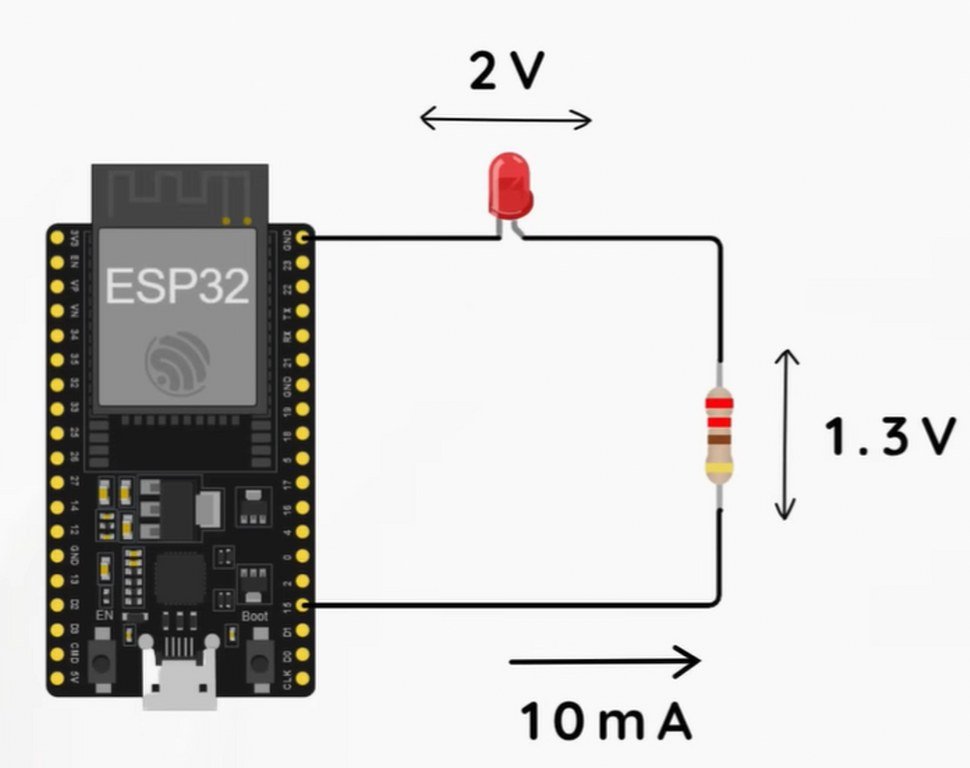
Let’s assume we’re using:
- An ESP32 running at 3.3 V
- A red LED with a 2 V forward voltage
- Desired LED current of 10 mA (0.01 A)
Since the LED uses approximately 2 V, the resistor must drop the remaining voltage:
Voltage across resistor = 3.3 V − 2.0 V = 1.3 V
Applying Ohm’s Law:
R = V / I
R = 1.3 / 0.01 = 130 Ω
Since 130 Ω isn’t a commonly available resistor value, you would simply choose the nearest standard value, such as 150 Ω or 220 Ω.
What Happens If You Choose the Wrong Resistor?
The resistor value directly affects how much current flows through the LED.
A larger resistor (for example, 330 Ω) allows less current to flow, making the LED slightly dimmer while remaining perfectly safe.
A smaller resistor, on the other hand, allows more current to flow. The LED becomes brighter, but both the LED and the ESP32 GPIO pin are subjected to higher electrical stress. If the resistance is too low, permanent damage can occur.
This is why beginner projects commonly use 220 Ω or 330 Ω resistors. They provide a good balance between brightness and safety for most standard indicator LEDs.
3. Potentiometer
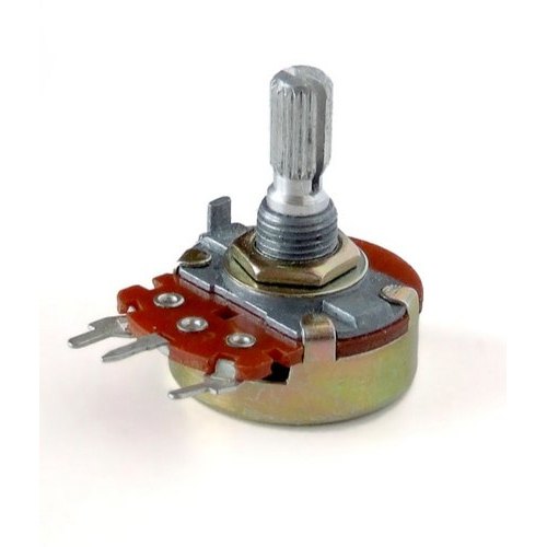
Imagine being able to control the brightness of an LED simply by turning a knob. No buttons, no complicated code—just a smooth adjustment from dim to bright. That’s exactly what a potentiometer allows you to do.
Potentiometers are among the most commonly used input devices in electronics. Whether you’re adjusting the volume on a speaker, controlling the speed of a motor, or changing the brightness of an LED, chances are a potentiometer is doing the job behind the scenes.
What Is a Potentiometer?
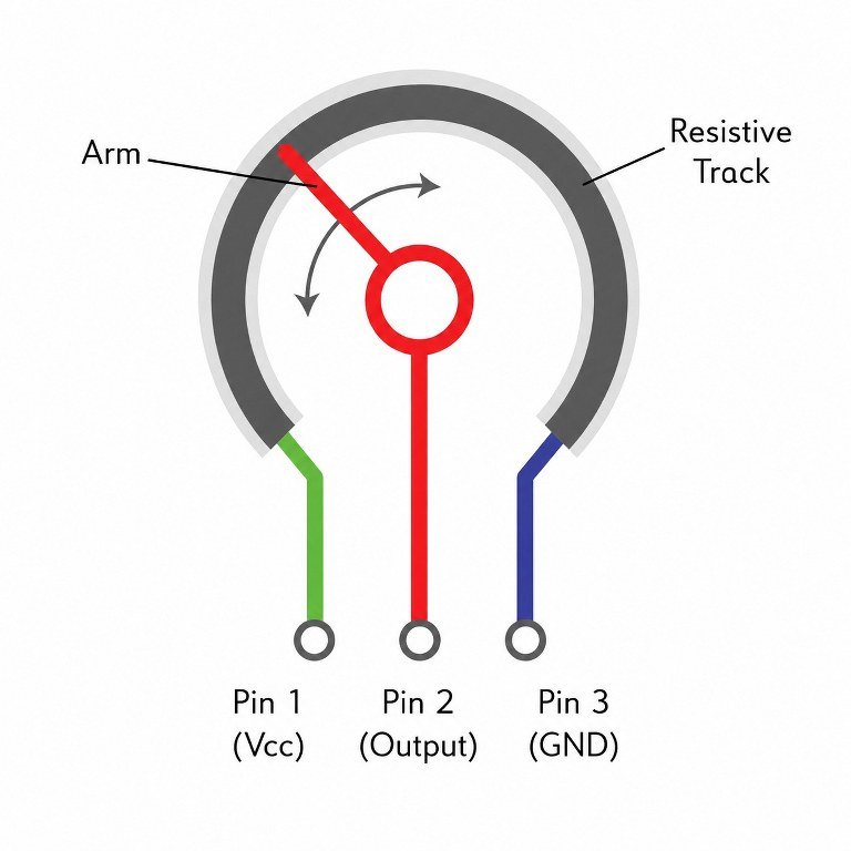
A potentiometer (often shortened to pot) is a variable resistor with three terminals.
Inside the potentiometer is a resistive track connected between the two outer terminals. The middle terminal, known as the wiper, slides along this resistive track as the knob is rotated.
As the wiper moves, the voltage available at the middle pin changes continuously, making the potentiometer an excellent component for generating adjustable voltages.
How Does It Work?
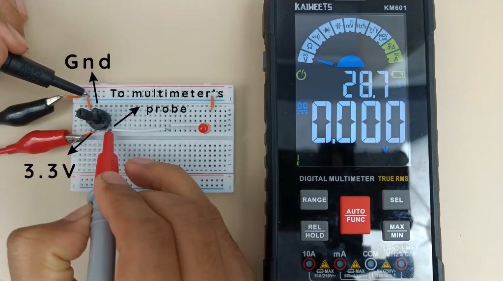
To understand how a potentiometer works, connect one outer terminal to 3.3 V and the other to ground. Now measure the voltage at the middle terminal using a multimeter.
As you rotate the knob, the voltage smoothly changes from 0 V to 3.3 V.
This happens because the potentiometer divides the supply voltage into two parts. Depending on the position of the wiper, the middle pin outputs a different fraction of the supply voltage.
For this reason, a potentiometer is often described as an adjustable voltage divider.
Potentiometer with an ESP32
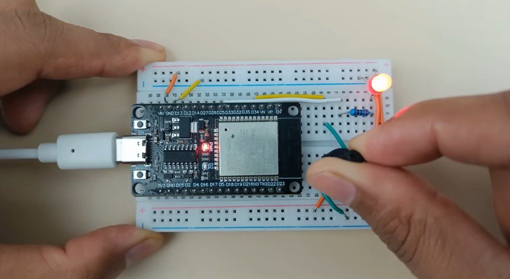
One of the most common uses of a potentiometer is providing analog input to a microcontroller.
The middle terminal of the potentiometer is connected to one of the ESP32’s analog input pins (ADC pin). As the knob is rotated, the voltage at this pin changes continuously.
The ESP32 measures this changing voltage using its built-in Analog-to-Digital Converter (ADC) and converts it into a digital value that your program can understand.
Your code can then use this value to control almost anything, including:
- LED brightness
- Servo motor position
- Motor speed
- Buzzer frequency
- LCD menu selection
- Sensor calibration values
In the demonstration circuit, the changing voltage is used to control the brightness of an LED. Rotating the knob increases or decreases the voltage at the analog input, and the ESP32 adjusts the LED brightness accordingly. The higher the input voltage, the brighter the LED becomes.
4. Capacitor
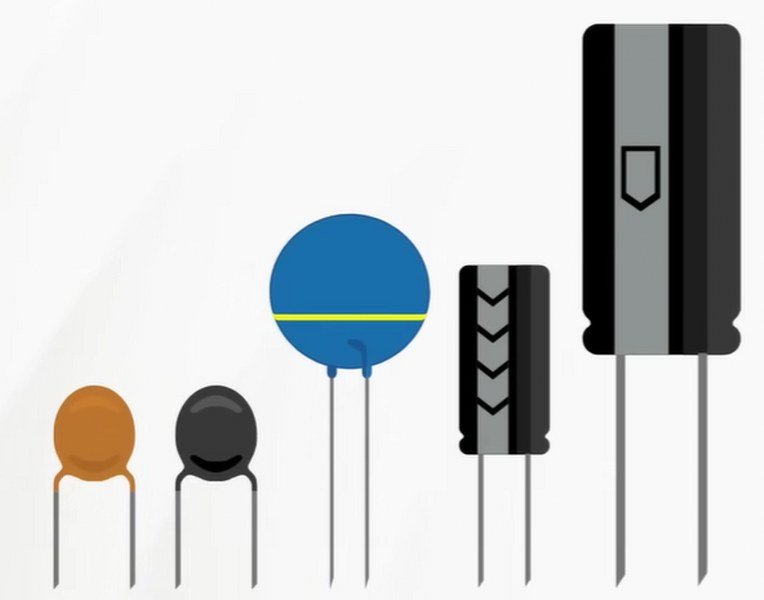
Take a look at the schematic of almost any ESP32 or Arduino development board, and you’ll notice capacitors everywhere. Some are tiny ceramic capacitors placed close to the microcontroller, while others are larger cylindrical components connected near the power input.
If resistors are used to control the flow of current, what exactly do capacitors do?
Simply put, a capacitor stores electrical charge. Although it can’t replace a battery, it can store enough energy to keep a circuit running for a very short time whenever the supply voltage suddenly drops. This seemingly simple ability makes capacitors one of the most important components in modern electronics.
How Does a Capacitor Work?
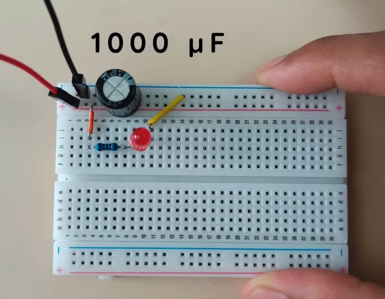
Imagine a simple LED circuit powered through a resistor. Now connect a 1000 µF capacitor across the power supply.
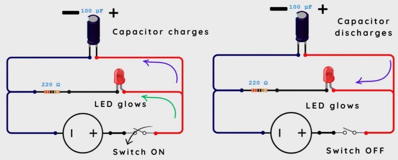
If the power supply is disconnected for a brief moment, you might expect the LED to turn off immediately. Instead, it gradually fades out over a short period.
Why?
While the power supply was connected, the capacitor stored electrical energy. As soon as the supply voltage disappeared, it began releasing that stored energy through the LED and resistor, keeping the circuit powered until the capacitor discharged.
Once the power is restored, the capacitor charges again and is ready to handle the next voltage dip.
Key Takeaway: A capacitor acts like a tiny energy reservoir, supplying power for a brief moment whenever the input voltage drops.
Why Are Capacitors Used on ESP32 and Arduino Boards?
Microcontrollers require a stable power supply to operate reliably. Even brief voltage fluctuations can cause unexpected behavior, communication errors, or random resets.
To prevent this, capacitors are placed across the power rails. Whenever the supply voltage momentarily dips, they release their stored energy and help keep the voltage stable until the power source recovers.
When capacitors are used for this purpose, they’re known as bypass capacitors or decoupling capacitors. This is by far the most common application you’ll encounter in ESP32 and Arduino circuits.
Why Doesn’t a Capacitor Discharge Instantly?
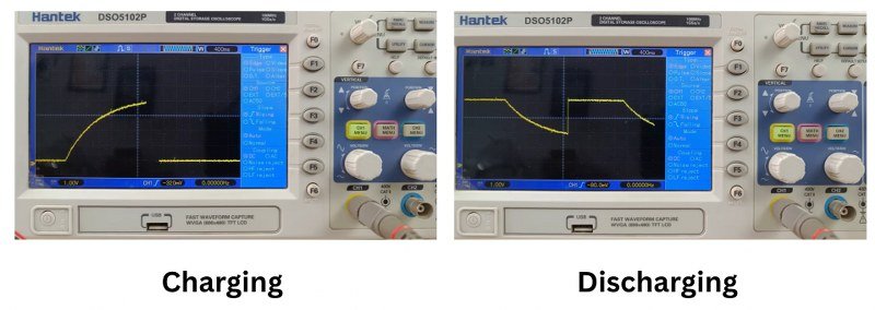
In the previous example, the LED didn’t switch off immediately—it faded away gradually.
That’s because a capacitor doesn’t release all its stored energy at once. Instead, its voltage decreases gradually over time as it discharges through the circuit.
Charging works in exactly the same way. A capacitor doesn’t instantly reach its full voltage either; it charges progressively.
The charging and discharging speed depends on two factors:
- The capacitance of the capacitor
- The resistance in the circuit
Together, these form what’s known as the RC time constant. A larger capacitance or higher resistance increases the charging and discharging time, while smaller values make the process much faster.
Other Common Uses of Capacitors
Although capacitors are best known for stabilizing power supplies, they have many other important applications.
Smoothing Power Supplies
Power supplies don’t always produce perfectly stable DC voltage. Small fluctuations, known as voltage ripple, are common.
Capacitors help smooth out these fluctuations, providing cleaner and more stable power to electronic circuits.
Coupling Signals
In audio and communication circuits, capacitors are often used as coupling capacitors.
They allow AC signals to pass while blocking unwanted DC voltage, making them useful for connecting different stages of an amplifier or signal-processing circuit.
Types of Capacitors You’ll Encounter
When working with ESP32 or Arduino projects, you’ll mainly come across two types of capacitors.
Ceramic Capacitors
Ceramic capacitors are the small components you’ll find scattered across almost every development board.
They are non-polarized, meaning they can be connected in either direction without any issues.
These capacitors are primarily used for bypassing and decoupling because they respond quickly to rapid voltage changes.
Electrolytic Capacitors
Electrolytic capacitors are much larger and typically have a cylindrical shape.
Unlike ceramic capacitors, they are polarized, which means orientation matters.
You can identify the terminals by looking at the capacitor:
- Long lead: Positive (+)
- Striped side: Negative (-)
Always connect electrolytic capacitors with the correct polarity. Reversing them can permanently damage the capacitor—and in extreme cases, cause it to fail dramatically.
5. Transistor
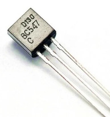
Earlier, we learned that an ESP32 or Arduino GPIO pin can safely supply only a limited amount of current. That’s perfectly fine for driving an LED, but what if you want to control a device that requires much more current, such as a relay, motor, or solenoid?
That’s where a transistor comes in.
A transistor acts as an electronic switch, allowing a tiny current from the microcontroller to control a much larger current flowing through an external circuit. This makes it one of the most important components in electronics and an essential building block for countless ESP32 and Arduino projects.
Why Can’t an ESP32 Drive a Relay Directly?
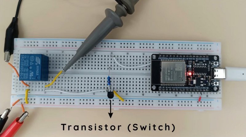
Consider a relay connected to an ESP32.
Although the ESP32 can easily generate the control signal needed to switch the relay on and off, the relay coil itself requires much more current than a GPIO pin can safely provide.
Instead of connecting the relay directly to the ESP32, a transistor is placed between the relay and ground.
Here’s what happens:
- The ESP32 outputs a HIGH signal.
- A small current flows into the transistor.
- The transistor turns on.
- Current from the external power supply flows through the relay coil.
- The relay is energized and switches on.
Notice that the high current never passes through the ESP32. It flows through the transistor instead, protecting the microcontroller from overload.
How Does a Transistor Work?
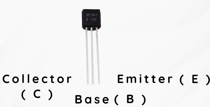
A standard NPN transistor has three terminals:
- Collector (C)
- Base (B)
- Emitter (E)
The base acts as the control terminal.
When a small current flows into the base, it allows a much larger current to flow from the collector to the emitter.
This is what makes a transistor such a powerful component—it uses a small input current to control a much larger output current.
A Small Current Controls a Bigger One
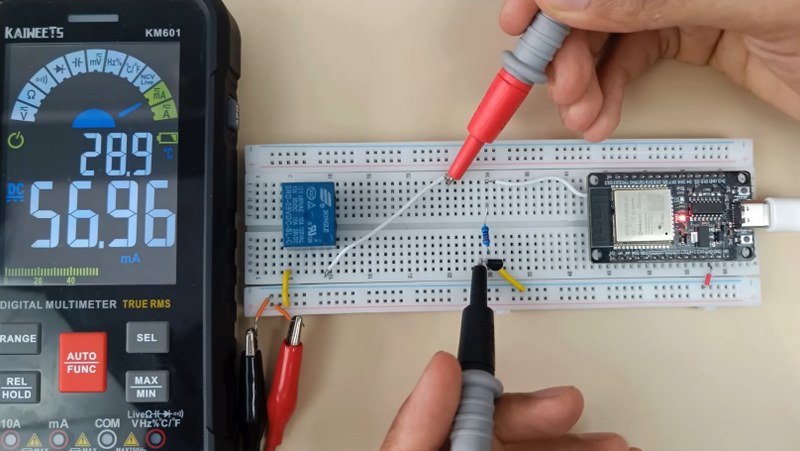
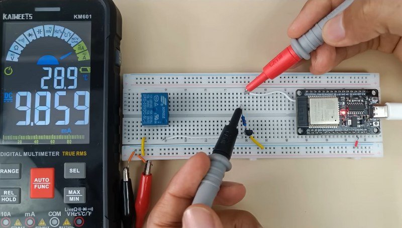
One of the easiest ways to understand a transistor is by comparing the current flowing through different parts of the circuit.
In the relay example, the relay draws approximately 57 mA when energized, while the ESP32 only needs to supply about 10 mA to the transistor’s base.
In other words, the GPIO pin isn’t powering the relay directly. Instead, it’s simply telling the transistor when to turn on or off.
Because of this behavior, a transistor is often described as a current-controlled switch. A relatively small current at the base controls a much larger current flowing through the load.
Why Is There a Resistor at the Base?
If you’ve looked at transistor circuits before, you’ve probably noticed a resistor connected between the GPIO pin and the transistor’s base.
This resistor serves the same purpose as the resistor used with an LED—it limits current.
Although the base requires only a small current to switch the transistor on, connecting it directly to the GPIO pin could allow excessive current to flow.
Adding a resistor ensures the base receives just enough current to operate safely while protecting both the transistor and the microcontroller.
6. Diode
If you’ve ever connected an LED the wrong way around, you’ve already seen one of the most important properties of a diode.
Connect it one way, and the circuit works perfectly. Reverse it, and nothing happens.
That’s because a diode is a semiconductor device that allows current to flow in only one direction. You can think of it as a one-way valve for electricity—it lets current pass in the forward direction while blocking it in the opposite direction.
How to Identify the Direction of a Diode

Most diodes have a silver or white band printed on one end.
This band marks the cathode (negative terminal).
Current flows from the anode to the cathode, so if the diode is connected in reverse, it simply blocks the current.
Unlike a resistor, the orientation of a diode matters. Connecting it backwards prevents the circuit from operating as intended.
Why Are Diodes Used with Relays?
One of the most important uses of a diode in ESP32 and Arduino projects is protecting switching circuits.
Let’s return to the relay circuit from the previous section.
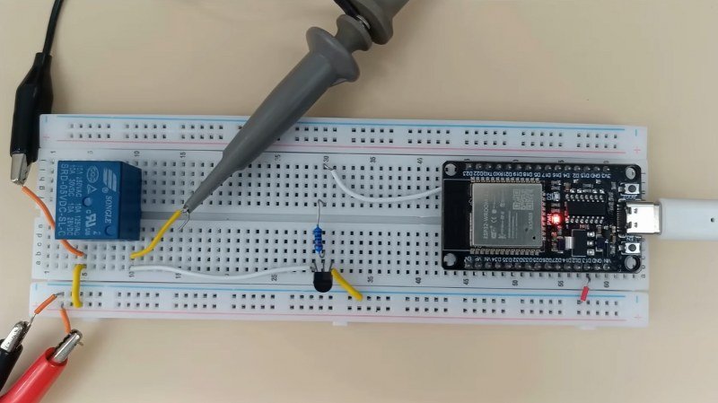
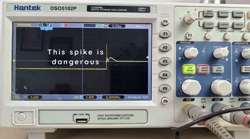
When the relay is switched on, current flows through its coil and creates a magnetic field. But the moment the relay is switched off, that magnetic field collapses.
As it collapses, the relay coil generates a high-voltage spike in the opposite direction.
This spike, often called back EMF, can easily damage the transistor, MOSFET, or even the ESP32 controlling the relay if no protection is provided.
How a Flyback Diode Protects the Circuit
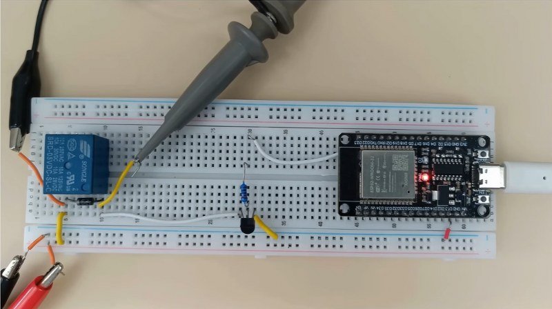
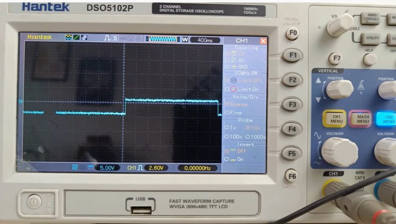
To prevent this voltage spike from damaging the circuit, a diode is connected directly across the relay coil.
When the relay turns off, the diode provides a safe path for the stored energy inside the coil.
Instead of traveling back toward the transistor or the ESP32, the current circulates through the relay coil and diode until the energy is safely dissipated.
Because of this role, the diode is commonly known as a flyback diode or freewheeling diode. You’ll find one across almost every relay, motor, solenoid, or other inductive load.
Key Takeaway: A flyback diode doesn’t do anything while the relay is ON. It becomes important only when the relay switches OFF and a voltage spike is generated.
Diodes in DC Motor Circuits
Relays aren’t the only components that need flyback protection.
DC motors also contain coils. When a motor is switched off suddenly, it generates the same kind of reverse voltage spike.
For this reason, you’ll often see a diode connected directly across the motor terminals.
Its job is exactly the same—to safely absorb the stored energy and prevent it from damaging the switching transistor or MOSFET.
Reverse Polarity Protection
Another important application of diodes is reverse current protection.
If you examine the schematic of many ESP32 development boards, you’ll notice a diode placed between the USB power input and the main power rail.
Why is it there?
Imagine powering the board through both USB and an external power supply at the same time. Without protection, current from the external supply could flow backward into your computer’s USB port.
The diode prevents this reverse current, protecting both the computer and the development board from potential damage.
7. MOSFET
Like a transistor, a MOSFET is an electronic switch that allows an ESP32 or Arduino to control devices requiring much more power than a GPIO pin can provide. However, in many applications, a MOSFET is the better choice because it’s more efficient, generates less heat, and can handle higher currents.
That’s why MOSFETs are widely used in motor drivers, LED controllers, battery-powered devices, and many other high-power electronic circuits.
How Does a MOSFET Work?
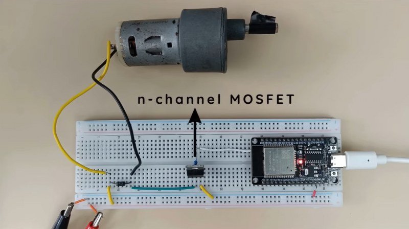
Imagine replacing the transistor in a DC motor control circuit with an N-channel MOSFET.
When the ESP32 outputs a HIGH signal, the MOSFET switches on, allowing current to flow through the motor. The motor starts spinning.
When the GPIO pin goes LOW, the MOSFET switches off, interrupting the current and stopping the motor.
Just like a transistor, the MOSFET acts as a switch between the power supply and the load. The difference lies in how it is controlled.
Transistor vs. MOSFET
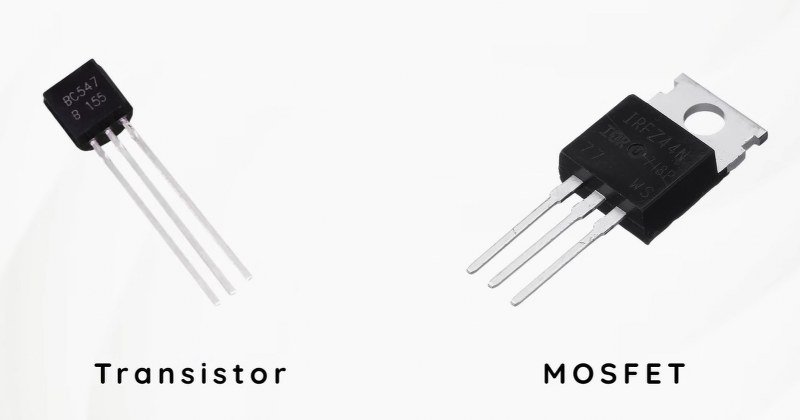
Although both components perform a similar function, they operate differently.
A bipolar transistor (BJT) is a current-controlled device. It requires a small but continuous current flowing into its base to remain switched on.
A MOSFET, on the other hand, is a voltage-controlled device. Instead of supplying continuous current, the ESP32 simply applies a voltage to the MOSFET’s gate, causing it to switch on.
Because the gate draws almost no continuous current, MOSFETs are generally much more efficient than transistors.
Think of it this way:
A transistor needs a small current to keep the switch closed, while a MOSFET mainly needs the correct voltage on its gate.
MOSFET Terminals
Like a transistor, a MOSFET has three terminals, but their names are different:

- Gate (G) – Control terminal
- Drain (D) – Current enters here
- Source (S) – Current exits here
The gate is equivalent to the transistor’s base. Applying the appropriate voltage to the gate turns the MOSFET on, allowing current to flow between the drain and the source.
Why Are MOSFETs Preferred?
If both transistors and MOSFETs can switch loads, why are MOSFETs so widely used?
There are several reasons.
1. Lower Power Consumption
Since the gate requires almost no continuous current, the ESP32 doesn’t have to waste energy driving the MOSFET.
This makes MOSFETs particularly useful in battery-powered devices where efficiency is important.
2. Less Heat Generation
When fully switched on, a MOSFET has a very low resistance between its drain and source.
Because of this, much less power is lost as heat compared to many small transistors.
Lower heat means better efficiency and higher reliability, especially when switching larger loads.
3. Higher Current Capability
Another major advantage is that MOSFETs can handle significantly higher currents than most small-signal transistors.
That’s why they’re commonly used in applications such as:
- DC motor controllers
- LED strips
- Battery-powered devices
- Power supplies
- High-current switching circuits
For smaller loads such as relays, buzzers, or a few LEDs, however, a standard transistor is often perfectly adequate.
Choosing the Right MOSFET
One important thing to remember is that not every MOSFET is suitable for ESP32 or Arduino projects.
The ESP32 outputs only 3.3 V from its GPIO pins, while many MOSFETs are designed to operate with much higher gate voltages.
If you use an unsuitable MOSFET, it may never turn on completely. Instead, it remains partially conducting, causing excessive heat and poor performance.
Before selecting a MOSFET, always check its datasheet and look at the gate threshold and recommended gate drive voltage.
Use Logic-Level MOSFETs
For ESP32 and Arduino projects, you should always choose a logic-level MOSFET.
These MOSFETs are specifically designed to switch fully using the 3.3 V or 5 V output available from a microcontroller GPIO pin.
Using a logic-level MOSFET ensures the device operates efficiently, stays cool, and delivers the expected performance.
8. Relay
Throughout this guide, we’ve used relays as examples when discussing transistors and diodes. The transistor switched the relay, and the diode protected the circuit from voltage spikes. But what exactly is a relay, and why is it still widely used when we already have transistors and MOSFETs?
The answer lies in one of its biggest advantages—electrical isolation.
A relay allows a low-voltage microcontroller like an ESP32 or Arduino to safely control high-voltage or high-current devices without any direct electrical connection between the two circuits.
What Is a Relay?
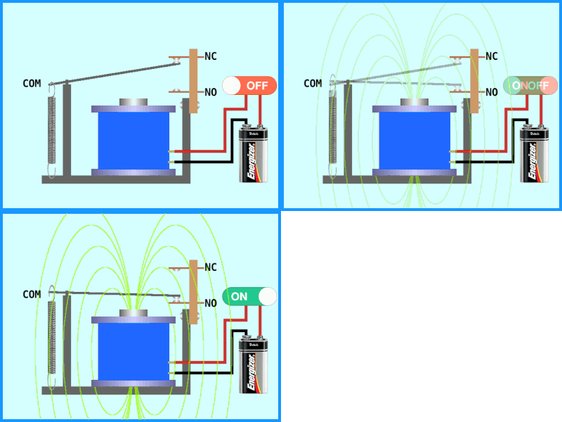
A relay is an electrically operated switch.
Unlike a transistor or MOSFET, which switches electronically, a relay contains a mechanical switch inside.
When voltage is applied to the relay’s coil, it creates a magnetic field that pulls a metal contact into a new position. Removing the voltage allows a spring to return the contact to its original position.
This simple mechanism allows a low-power control circuit to operate an entirely separate high-power circuit.
Why Use a Relay?
Imagine you want to control a 230 V AC light bulb using an ESP32.
Can you connect the bulb directly to the ESP32?
Absolutely not.
The GPIO pins operate at just 3.3 V and are designed to supply only a small amount of current. Connecting them directly to mains electricity would not only damage the board but also create a serious safety hazard.
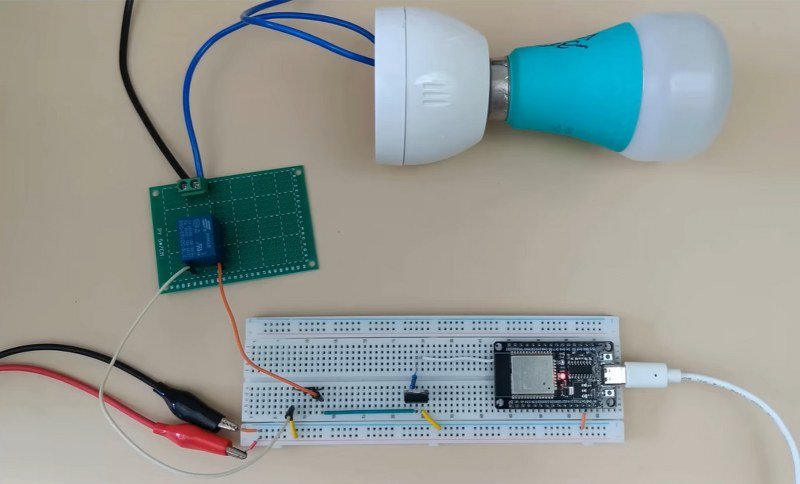
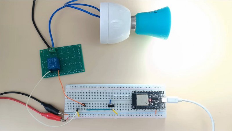
Instead, the ESP32 simply energizes the relay’s coil through a transistor or MOSFET. The relay then switches the separate AC circuit completely independently.
The two circuits never share a direct electrical connection. This separation is known as electrical isolation, and it’s one of the primary reasons relays remain so popular in automation and industrial control systems.
Key Takeaway: The ESP32 controls only the relay coil. The relay safely switches the high-voltage load.
Understanding Relay Pins
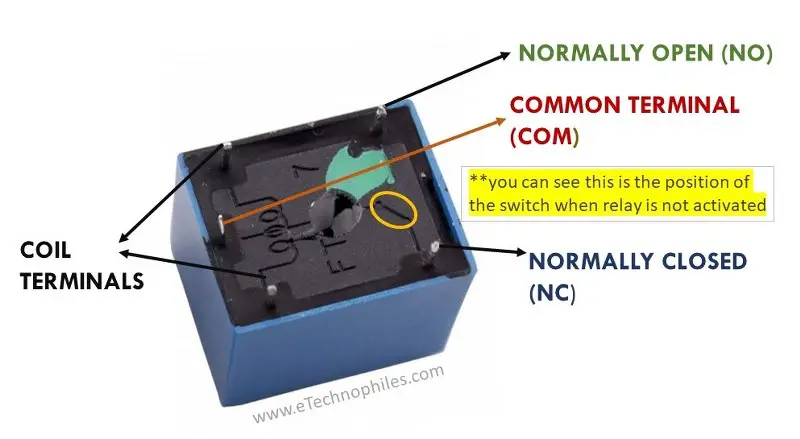
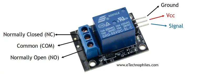
Most standard relays have five terminals.
Two terminals are connected to the electromagnetic coil, while the remaining three form the switching contacts:
- COM (Common)
- NO (Normally Open)
- NC (Normally Closed)
When the relay is OFF, the COM terminal is connected to NC.
When the relay is ON, the electromagnet pulls the internal contact, disconnecting COM from NC and connecting it to NO instead.
This allows you to choose whether a device should remain ON or OFF by default, depending on your application.
What Is a Solid-State Relay?

Not all relays contain moving parts.
A Solid-State Relay (SSR) performs the same basic function but uses electronic components instead of mechanical contacts.
Compared to mechanical relays, SSRs offer several advantages:
- Silent operation
- Faster switching
- Longer lifespan due to the absence of moving parts
However, they are generally more expensive and are typically used in applications where these benefits justify the additional cost.
Relay Modules
In most beginner ESP32 and Arduino projects, you won’t use a bare relay.
Instead, you’ll use a relay module.
A relay module already includes many of the supporting components needed to operate the relay safely, including:
- A transistor driver
- A flyback diode
- An indicator LED
- Current-limiting resistors
This means you can connect the module directly to your microcontroller without having to design the driver circuit yourself. For beginners, a standard 5 V electromechanical relay module is by far the most common choice.
