Last updated on March 26th, 2024 at 04:16 pm
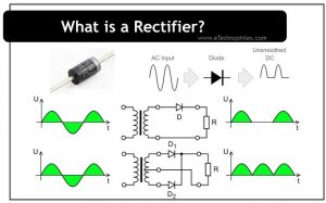
In our previous article, we discussed what a rectifier diode is. In this one, we will look at the rectifier circuits. A rectifier circuit converts alternating current (AC) to Direct current (DC). Generally, two rectifiers are used for rectification, i.e., a Half-wave rectifier and a Full-wave rectifier.
Table of Contents
Half wave rectifier
Half wave rectifier converts sinusoidal AC signal into pulsing DC by blocking either positive or negative cycle. This depends on the orientation of the diode connected to the circuit. Let us understand this with the help of an example.
Positive half wave

In this configuration, the diode only conducts when it gets forward-biased. In simple words, when the positive cycle of a sinusoidal wave approaches the diode, it gets forward biased and allows the current to pass. But when the negative cycle of the sinusoidal wave approaches the diode, it gets reverse biased and hence blocks it.


The above figure shows input and output waveforms. As the negative half of the AC waveform is not present at the output, this circuit configuration is known as a positive half wave rectifier.
Negative half wave

If a diode is connected in this configuration, it conducts only when it gets forward-biased. When a positive half cycle of a sinusoidal wave approaches the diode, it gets reverse biased and blocks it. But when the negative cycle of the sinusoidal wave approaches the diode, it gets forward-biased and allows it to pass.

In this case, if we observe the output waveform, only the negative cycles of the sinusoidal wave are present. Hence, this circuit configuration is known as a negative half rectifier.
What is the need for a filter capacitor?
If we observe the output waveforms in the above two cases, they are not pure DC waveforms. Instead, they contain ripples. So, a capacitor is connected at the output (parallel to the load) to suppress the ripples of a DC voltage. This is called a filter capacitor.
The capacitor gets charged up to its maximum voltage when the diode gets forward-biased. When the diode gets reverse-biased, the capacitor discharges and provides the required current to the load. The waveform present below shows how the output waveform gets smoothened after using a filter capacitor.

It should be noted that the waveform is still not pure DC. For that, we use a more efficient rectifier, aka Full-wave rectifier.
Advantages
- The construction is simple
- Only a few components are required
Disadvantages
- Power loss is more
- More ripples are present at the output
What is the ripple factor?
Before we move on, let us understand an important concept, i.e., the ripple factor. The ripple factor measures the ripples present in the output DC signal. So, if the ripples are more, the ripple factor will be high and vice-versa.
The ripple factor of a half-wave rectifier comes out to be 1.21. In other words, the unwanted ripple present in the output along with the DC voltage is 121% of the DC magnitude. This indicates that the half-wave rectifier is not an efficient AC-to-DC converter. The rectification efficiency for a halfwave rectifier is 40.6%.
Full wave rectifier
To reduce the ripples at the output a more efficient rectifier, i.e., a full-wave rectifier is used. It converts the complete cycle of the input AC signal to pulsating DC. There are two types;
- Center tap full wave
- Full wave bridge
Center tap full wave
The figure below shows the connection of the center-tap full wave rectifier. Two diodes are connected to the secondary winding of the transformer. A center tap is taken from the transformer to which a load (RL) is connected.

During the positive half-cycle

End A of secondary winding becomes positive and end B negative. The diode D1 gets forward-biased (acts as a closed switch) and diode D2 gets reverse-biased (acts as an open switch). Therefore, current flows through the load (RL) from P to O.
During the negative half-cycle

During the negative half cycle of input AC supply, the end B of secondary winding becomes positive and end A negative. In this case, the diode D2 gets forward biased (acts like a closed switch) and the diode D1 gets reverse biased (acts like an open switch). Therefore, the current will flow from B to O through diode D2, load RL, and the lower half of the secondary winding.

If we observe the output waveform, a pulsated DC output is present during both positive half and negative half cycles. Hence, by using this setup, the ripples are reduced at the output. The ripple factor of the centre-tap full wave rectifier is 0.482, while the efficiency is 81.2%.
Advantages
- Higher efficiency than half-wave rectifiers
- Low ripple factor
Disadvantages
- Difficult to locate the center tap on the transformer.
Full wave bridge
It eliminates the need for a center-tapped transformer, as it uses a step-down transformer. Along with it, four diodes, and an electrical load are required. The figure below shows the appropriate connection. The diodes are arranged in series pairs, i.e., two diodes conduct during each cycle. Let us how it works.

During the positive half-cycle

During the positive half cycle of the supply, the end A (secondary winding of transformer) becomes positive while the end B becomes negative. In this case, diodes D1 and D3 gets forward biased, and creates a short path for current. The diodes D2 and D4 get reverse-biased and create an open circuit. The figure above shows the path followed by the current.
During the negative half-cycle

During the negative half cycle of the supply, the end A becomes negative while the end B becomes positive. In this case, diodes D2 and D4 gets forward biased, and creates a short path for current. The diodes D1 and D3 gets reverse-biased, and create an open circuit. The figure above shows the path followed by the current.
If we observe here, in both the cycles of input AC supply, the current flows through load RL in the same direction. Hence, DC output is obtained across the load. The efficiency and ripple factor for bridge full wave rectifiers is the same as center tap full wave rectifiers.
Full wave rectifier with smoothening capacitor
If we observe the output waveform of a full wave rectifier, it is not pure DC. A capacitor can be connected to the output of a full wave rectifier to smoothen the pulsating DC output. The figure below shows the output from the smoothening capacitor filter.

Advantages
- The need for a center tap transformer is eliminated.
- The output is double that of the center-tapped full-wave rectifier (for the same secondary voltage).
- The peak inverse voltage across each diode is one-half of the center tap circuit of the diode.
Disadvantages
- The circuit is not suitable when a small voltage is required to be rectified. It is because, in this case, the two diodes are connected in series and offer double voltage drop due to their internal resistance.