Last updated on March 16th, 2024 at 04:24 pm
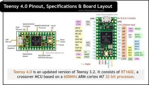
Teensy 4.0 is an updated version of Teensy 3.2. The thing that makes this board so powerful is RT1602, a crossover MCU based on a 600MHz ARM cortex M7 32-bit processor. The board comes with 1024 KB RAM, 1984 KB flash memory, and 1KB EEPROM.
There are 14 analog pins and 40 digital I/O pins on board out of which 31 pins support pulse width modulation.
Table of Contents
Specifications
The Cortex-M7 processor in the Teensy board is a dual-issue superscalar, which means it can execute two instructions per clock cycle at 600MHz. It even includes a floating point unit (FPU) that supports both 64-bit “double” and 32-bit “float.” More specifications are listed in the table below:
| Specifications | Description |
| MCU | MIMXRT1062DVL68 ARM Cortex-M7 MCU |
| RAM | 1024KB RAM (From which 512KB is tightly coupled) |
| Flash Memory | 1984KB |
| EEPROM | 1KB |
| USB Port | 2 USB ports are available and the speed of both is 480 MBit/sec |
| CAN Bus | 3 CAN Bus present |
| I2S | 2 I2S Digital Audio |
| SPI | 3 SPI ports are available |
| I2C | 3 I2C ports are available |
| Serial Ports | 7 Serial Ports are available |
| Digital I/O Pins | 40 |
| PWM Pins | 31 |
| Analog Input Pins | 14 |
| DMA | 32 general-purpose DMA channels |
| ADC | 2 ADC’s available |
| RTC | Yes, RTC is available in Teensy 4.0 |
| DC Current Per I/O Pin | 10mA |
| Operating Voltage And I/O voltage compatibility | 3.3V |
| Cryptographic Acceleration | Yes, Cryptographic Acceleration is present in teensy 4.0 |
Board layout

MCU (MIMXRT1062DVL68)
The MCU in Teensy 4.0 is from the MX RT1060 processor family. It runs at a speed of up to 600 MHz to provide high CPU performance and the best real-time response. On-chip RAM for the i.MX RT1060 processor is 1 MB. The first 512 KB can be configured as general-purpose on-chip RAM, while the second 512 KB is general-purpose on-chip RAM.
Controller (MKL02Z32VFG4)
It is the secondary microcontroller present on the Teensy 4.0 board. This increase the overall efficiency and performance of the board. It has a small size, ultrasmall package, and energy-efficient ARM Cortex-M0+ 32-bit performance. This microcontroller provides the following:
- Run power consumption as low as 36 A/MHz in very low power run mode
- Static power consumption down to 2 μA with full state retention(fast wake-up address) and 4 μs wakeup
- Ultra-efficient Cortex-M0+ processor running at up to 48 MHz with industry-leading throughput
- Memory options include up to 32 KB flash and 4 KB RAM
Mosfet (DMG2305UX)
The MOSFET on the board is optimized for high-efficiency power management applications. It minimizes the on-state resistance while maintaining superior switching performance.
Regulator (TLV75733P)
It is a low-dropout regulator (LDO). The TLV757P is designed for a wide range of applications, with an input voltage range of 1.45 V to 5.5 V. To support the lower core voltages of modern MCUs, the device is available in fixed output voltages ranging from 0.6 V to 5 V to reduce cost and board’s size. For teensy 4.0 we require a 3.3V regulated voltage.
Serial Flash Memory (W25Q16JVUXIM)
It is external Serial Flash memory used with the central MCU. This provides external flash memory to the board.
Read also: Teensy 3.2 Pinout, Specifications & Board Layout
Pinout
In Teensy 4.0 there are 14 analog pins and 40 digital I/O pins on board out of which 31 pins support pulse width modulation. The table below gives the Pinout of Teensy 4.0.


| Pin Category | Pin name | Description |
| Power | VIN, 3.3V, GND | VIN – This pin may receive 5V when USB power is not used. (3.6 to 5.5V) 3.3V – The onboard regulator’s regulated output voltage (250mA max) GND stands for ground pins. |
| Analog Pins | A0 – A9 Pin 14-23 A10-A13 Pin 24-27 | Pins A0 to A9 can be used as analog inputs with a resolution of 12 bits |
| I/O Pins | D0 – D23 | 40 Digital I/O Pins are available.24 are easily accessible when used with a solderless breadboard |
| PWM Pins | D0 – D15 D18 – D19 D22 – D23 D24 – D25 D28 – D29 D33-D39 | 31 PWM output pins |
| Inbuilt LED | D13 | Inbuilt GPIO indicator LED |
| Serial Com. | TX1 , RX1: Pin 1,0 TX2 , RX2: Pin 8,7 TX3 , RX3: Pin 14,15 TX4 , RX4: Pin 17,16 TX5 , RX5: Pin 20,21 TX6 , RX6: Pin 24,25 TX7 , RX7: Pin 29,28 | 7 serial ports are available |
| SPI | CS, MOSI, MISO, SCK : Pin 10,11,12,13 CS2,MOSI2,MISO2,SCK2 :Pin 36,35,34,37 | Serial Peripheral Interface port |
| I2C | SCL0 , SDA0: Pin 19,18 SCL1 , SDA1: Pin 16,17 SCL2, SDA2: Pin 24,25 | Inter-Integrated Circuit communication port |
| CAN Bus | CTX1 , CRX1: Pin 11,13 CTX2 , CRX2: Pin 1,0 CTX3 , CRX3: Pin 31,30 | CAN bus (1 with CAN FD) |
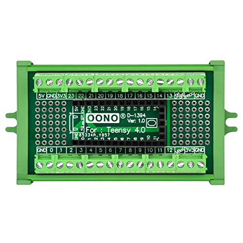
- Terminal Block Breakout Board Module for Teensy 4.0, Screw Mount Version. With the breakout board, you can easily extend Teensy 4.0 projects to industrial control, home automation or other applications.
- With 107 DIY solder pads on board, pitch 2.54mm, hole 0.8mm, you can use these pads to install soldered some electronic components for you need.
How to power Teensy 4.0?
- USB Power
Teensy is powered by your PC or USB hub via a USB cable. The USB power is delivered to the VUSB pin, which is linked to VIN and powers the entire board.
- VIN PIN
When not using USB power, 5V power can be applied to the VIN pin. Because VIN and VUSB are linked, power should not be applied to VIN while using a USB cable to avoid power flowing back into your computer.
- 3.3V Power
The Teensy 4.0 includes a voltage regulator that reduces the 5V VUSB / VIN power to 3.3V for use by the main processor and most other components. The 3.3V pin can be used to power additional circuitry. The maximum current rating is 250mA.
- Power Consumption
Teensy 4.0 consumes approximately 100 mA current when operating.
Teensy 4.0 Schematic

Teensy 4.0 has a 32-bit ARM Cortex-M7 CPU running at 600MHz as the primary microcontroller. It also has a secondary microcontroller, i.e., 48MHz Cortex-M0+ Ultra-Low Power MCU with 32KB Flash and 4KB SRAM. This is used for signal multiplexing, decreasing wake-up time, and increasing the overall performance of the Teensy 4.0 development board.
The controller runs at 600Mhz but still, a 24Mhz external crystal oscillator is added to increase the overall clock frequency. Another crystal oscillator is used for the Real Time Clock. There are two LEDs present: one is for showing power status and the second one is an inbuilt led connected to the 13th pin. A USB Micro-AB type socket is used to connect the USB cable for programming the board and to power up the board.
Projects using Teensy 4.0
Teensy 4.0 YouTube Animation
Using teensy 4.0 you can connect TFT displays and make really nice animations according to your requirement and also the speed of the board is also fast than other microcontrollers boards. To view, click here.
Teensy 4.0 Convolution SDR
- You can make convolution SDR using a Teensy 4.0 microcontroller, ADC PCM1808, DAC PCM5102a, TFT ILI9341, and a quadrature sampling detector board (Joris, kthkit) with the Si5351 oscillator.
- The ADC is overclocked to 256ksps sample rate to enable FM Stereo reception.
- The spectrum display shows the audio spectrum AFTER demodulation.
So this is also one of the cool projects that you can make using teensy 4.0. Click here to view the video.