A diode allows the flow of current in one direction only. So it acts like a closed switch(with some resistance) in one direction called forward bias configuration, and an open switch in the opposite direction called reverse bias configuration.
It’s easy to test a diode. You have to just check the flow of current through the diode in forward and reverse bias. There is a built-in function in digital multimeters for this called ‘Diode test’ mode. If the multimeter does not have this function available, the resistance method can also be used to test a diode.
| Diode condition | Diode test mode | Resistance mode |
|---|---|---|
| Good diode | Fwd bias: 0.2V to 0.8V Reverse bias: ‘OL’ | Fwd bias: 1KΩ TO 1MΩ Reverse bias: ‘OL’ |
| Bad diode | Fwd bias: 0 to 0.4V Reverse bias: 0 to 0.4V or ‘OL’ in both cases. | Same value in both config. |
Table of Contents
How to test a diode using a multimeter?
Identify the terminals of the diode
Before testing a diode, you need to identify its terminals. Diodes are typically cylindrical in shape, with a band or stripe on one end, usually in silver/white color. The terminal connected to this band is the cathode (-), while the other terminal is the anode (+).

Prepare Your Multimeter
Insert the red probe into the mAVΩ port and the black probe into the COM port on your multimeter. Then using the rotary dial, set your multimeter in the diode test mode (denoted by a diode symbol). You can also use the resistance mode to test a diode. We will discuss both methods in this article.

Note: Some multimeters have diode mode included with one of the resistance ranges(mostly with 2K ohm range). Whereas some multimeters have diode and continuity modes together.
Isolate the Diode
To get accurate readings, ensure that the diode is isolated from the circuit. Disconnect it or remove it from the circuit if possible, making sure there is no electrical connection to the rest of the circuit.
Check the Diode in Forward Bias
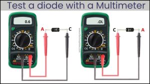
Place the red probe of your multimeter on the diode’s anode (+) terminal and the black probe on the cathode (-) terminal. In this forward bias configuration, a good diode should display a voltage drop (typically between 0.2 to 0.7 volts), indicating that it allows current to pass in this direction.

Check the Diode in Reverse Bias
Next, reverse the probe positions. Place the red probe on the cathode (-) and the black probe on the anode (+). The multimeter should display ‘OL’, because in this reverse bias configuration, a functioning diode acts as an open switch. This means that it’s blocking current flow in the reverse direction properly.

Analyze the Readings
Based on your readings in both forward and reverse bias, you can draw conclusions about the diode’s health.
Diode is good if:
- In forward bias, the multimeter displays the voltage between 0.5V to 0.8V for a Silicon diode and 0.2 to 0.3 for a germanium diode.
- The multimeter displays ‘OL’ (open loop) or 1 in reverse bias.
Diode is faulty if:
- In both configurations, the voltage value is between 0V to 0.4V. This means that the diode is shorted.
- Multimeter displays ‘OL’ in both configurations. This means that the diode is open.
How to test a diode using the resistance mode?
If your multimeter doesn’t have a diode test mode, you can still check a diode’s health using the resistance mode. But please note that this method does not give conclusive evidence about the state of the diode. Thus, diode mode is the recommended method.
Make sure the diode under test is completely isolated and not connected anywhere.
Select the resistance mode
Using the rotary dial, set your multimeter in the resistance mode (denoted by Ω ohm symbol). In the ideal state, the multimeter displays “1” or “OL”. Touch the probes together. The multimeter should display “0” in this case, indicating 0 resistance.
There are different resistance ranges on a multimeter, usually 200Ω, 2kΩ, 20kΩ, 200kΩ and 2MΩ. A good diode has a forward bias resistance between 1KΩ to 1MΩ. So you should select the highest range available, 2MΩ in this case.

Check the Diode in Forward Bias
Place the red probe of your multimeter on the diode’s anode (+) terminal and the black probe on the cathode (-) terminal. In this forward bias configuration, a good diode should display resistance between 1KΩ-1MΩ, indicating that it allows current to pass in this direction.
Check the Diode in Reverse Bias
Next, reverse the probe positions. Place the red probe on the cathode (-) and the black probe on the anode (+). The multimeter should display ‘OL’, because in this reverse bias configuration, a functioning diode acts as an open switch. This means that it’s blocking current flow in the reverse direction properly.
Analyze the resistance readings
Diode is good if:
- In forward bias, the resistance is between 1KΩ to 1MΩ.
- In reverse bias, the multimeter displays ‘OL’ or ‘1’.
Diode is faulty if:
- In both cases, the multimeter displays similar values.