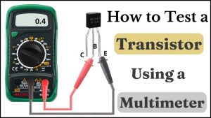
A transistor is a three-terminal device. The three pins are called Emitter, Base, and Collector. The main function of a transistor is to regulate the high current flowing between the emitter and collector by applying a small current at the base.
It is made up of two PN junctions joined together. A transistor with a PN junction followed by an NP junction is called a PNP transistor, while an NP junction followed by a PN junction results in an NPN transistor.
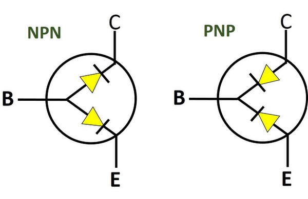
Since the PN junction is a diode, a transistor is like a pair of diodes with their Anode(NPN) or Cathode(PNP) connected together. So, to test a transistor using a multimeter, you can measure the voltage drop between its terminals, similar to a diode test.
Table of Contents
How to test a transistor with a multimeter?
Measure the voltage drop between every pair of terminals in diode test mode- B and E, B and C, E and B, C and B, and C and E. Compare the values with the readings given below.
| Voltage between | NPN transistor | PNP transistor |
|---|---|---|
| Base and Emitter | 0.4V to 0.9V | OL |
| Emitter and Base | OL | 0.4V to 0.9V |
| Base and Collector | 0.4V to 0.9V | OL |
| Collector and Base | OL | 0.4V to 0.9V |
| Collector and Emitter | OL | OL |
| Emitter and Collector | OL | OL |
If the voltage drops between any of the terminals deviates from the value given above, the transistor is most likely bad.
For a step-by-step guide on testing the transistor using a multimeter, keep reading.
Step 1: Identify the transistor type and its pinout
Look at the part number printed on the transistor casing and search for it on Google. Find out if it is an NPN type or a PNP type.
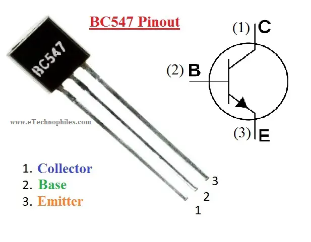
The next step is to identify its terminals. Look at the datasheet for the pinout or search on Google, ‘xxxxx pinout’. Only when you know which terminal is which, continue with the next step.
Step 2: Set the multimeter in the diode mode
Insert the red probe into the mAVΩ port and the black probe into the COM port on your multimeter. Then using the rotary dial, set your multimeter in the diode test mode (denoted by a diode symbol).
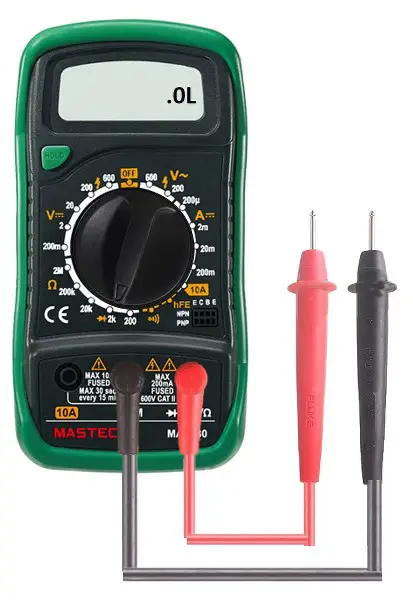
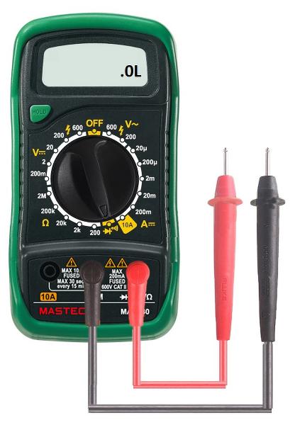
Note: Some multimeters have diode mode included with one of the resistance ranges(mostly with 2K ohm range). Whereas some multimeters have diode and continuity modes together.
Step 3: Isolate the transistor
Turn off the supply to the circuit and make sure no voltage or current is flowing through the transistor. If there is a capacitor nearby, discharge it. If possible, take out the transistor and place it on a bench.
Step 4: Perform the diode test
It’s time to measure the voltage drop between different terminals starting with:
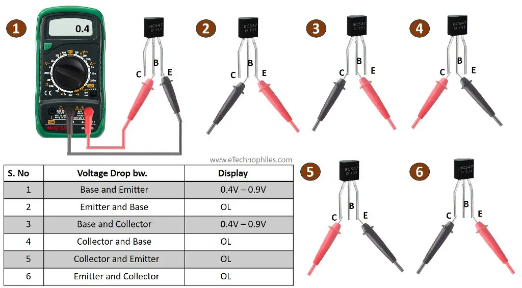
Base and emitter: Touch the red probe to the base terminal and the black probe to the emitter terminal.
For an NPN transistor, this is the forward bias configuration of the base-to-emitter PN junction. So, the ideal voltage should be between 0.4 to 0.9 volts.
For a PNP transistor, this is the reverse bias configuration of the emitter-to-base PN junction. So, there should be an open circuit, and the multimeter should display ‘OL’ or ‘1’.
Emitter and base: Swap the probes. Red touching the emitter and black touching the base terminal.
For an NPN transistor, this is the reverse bias configuration of the base-to-emitter PN junction. So, there should be an open circuit, and the multimeter should display ‘OL’ or ‘1’.
For a PNP transistor, this is the forward bias configuration of the emitter-to-base PN junction. So, the ideal voltage should be between 0.4 to 0.9 volts.
Base and collector: Touch the red probe to the base terminal and the black probe to the collector terminal.
For an NPN transistor, this is the forward bias configuration of the base-to-collector PN junction. So, the ideal voltage should be between 0.4 to 0.9 volts.
For a PNP transistor, this is the reverse bias configuration of the collector-to-base PN junction. So, there should be an open circuit, and the multimeter should display ‘OL’ or ‘1’.
Collector and base: Swap the probes. Red touching the collector and black touching the base terminal.
For an NPN transistor, this is the reverse bias configuration of the base-to-collector PN junction. So, there should be an open circuit, and the multimeter should display ‘OL’ or ‘1’.
For a PNP transistor, this is the forward bias configuration of the collector-to-base PN junction. So, the ideal voltage should be between 0.4 to 0.9 volts.
Collector and emitter: Now touch the red and black probe to the collector and base terminal, respectively.
For both NPN and PNP transistors, the multimeter should display ‘OL’.
Emitter and collector: Swap the probes.
For both NPN and PNP transistors, the multimeter should display ‘OL’.
Test analysis
If the voltage drop between any of the terminals is not equal to the expected voltage, then the transistor is not functioning properly. This test can detect only two types of faults: shorted and open.
- Expected voltage = 0.4 to 0.9 volts. Tested voltage = OL. The junction is open.
- Expected voltage = OL. Tested voltage = finite value. The junction is shorted.
