Last updated on April 2nd, 2024 at 11:35 am
Diodes are semiconductor components that are used to conduct current in the forward direction. Sometimes this characteristic (to show low impedance in forward bias and very high impedance in reverse bias) of diodes gives them an edge to use them as protective circuits.
With the same concept when we use it with an inductive load to protect flyback voltage spikes, we call it a flyback diode. In this article, we will discuss the uses of flyback diodes and their working principle in detail.
Table of Contents
What is a flyback diode?

It is also a simple P-N junction diode that is used to protect the circuit from the flyback voltage generated by the inductive load. The high voltage spike generated by the inductor due to sudden switching is called flyback voltage.
Some popular names for flyback diodes are Freewheeling, Snubber, Suppressor, Catch, and Commutating diode.
- Flyback voltages occur because of the Electro-Magnetic Induction and back emf properties of an inductor.
- Inductive kickback is the process of rapid change in voltage across an inductor when current flow is interrupted due to rapid switching in circuits.
Applications
Some major applications and circuits where flyback diodes are used are listed below:
- Circuits in which inductive loads are controlled by a switch
- Switching power supply and inverters
- Relay drivers
- H-bridge motor drivers
- Full wave rectifier
- Thyristor
- In minimizing the antenna-like radiation of the electromagnetic energy from wires connected to the inductor
Working principle
An inductor stores energy in the form of a magnetic field. To maintain a constant value of the current, an inductor always opposes any changes in the current passing through it. For that, it induces an EMF across it in the proportion of change in current.

Figure (a) shows a closed switch connected to an inductive load. When the switch is opened figure (b), a sudden change in the magnetic flux of the inductor coil occurs. This change in flux induces an emf in the inductor, and the voltage polarity gets reversed.

As inductors oppose a change in current, when the switch gets opened, the inductor tries to keep the current flowing in the same direction. Since the open switch gap acts as a very large air resistance(~MΩ), that’s why to maintain the same value of current as before, the inductor generates a very high voltage across the switch also known as flyback voltage.

These flyback voltage spikes are strong enough to create electrical sparks or arcs in the switching device (relay, transistor) which might damage the switch or other circuit components. So, to protect the switches due to flyback voltage sparks, we use a reverse-biased diode (flyback) connected parallel to the inductive load.
How do flyback diodes work in a circuit?
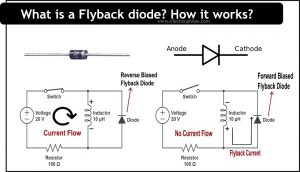
In the figure below, we can see that a reversed biased diode is connected parallel to the inductive load. When a flyback voltage spike arises in the circuit it acts as the flyback diode. Let’s see how it works.

- In Figure (a) when the switch is connected, it will be in reverse biased condition, so it will not allow the current to pass through it; hence, the diode acts as an open circuit.
- But in Figure (b) when the switch is disconnected, the voltage polarity of the inductor will get reversed. Now the diode becomes forward-biased and passes the current through it. A complete loop is formed and most of the flyback current gets dissipated in the loop rather than going to switch.
In this way, the flyback diode helps to divert the flyback current arising due to the induced back emf of an inductor and protects the switching device from heavy electrical sparks.

Advantages
The advantages are listed below:
- It decreases the harmonic sparking and protects the circuit from flyback voltage spikes.
- It enhances the load current of the circuit.
- It protects the rectifier circuit from extreme reverse voltage due to inductive load.
- It can enhance the input power factor in flyback converter circuits.
- It maintains the average output voltage and ripple component in the converter circuit.
FAQs
Are the flyback diodes and normal diodes the same?
Yes, they are the same. Both work on a similar principle, but the application of each is different. Flyback diodes are used to protect the switches from high voltage spikes and even their response time is very faster than normal diodes.
Is there any difference between the RC snubber circuit and the snubber diode circuit?
Yes, there is a difference between an RC snubber circuit and a snubber diode circuit. RC snubber circuits use a series combination of a resistor and a capacitor in parallel connection with inductive load to stop flyback voltage spikes.
The snubber diode or flyback diode is a simple p-n junction diode used in place of RC snubber to prevent switches from flyback voltage.
Do automotive relays have flyback diodes?
Automotive relays can be used with or without flyback diodes. However, it is preferable to use automotive relay circuits for their better safety and precautions.
Insert a zener diode in series wth diode, 2x supply voltage rating.
Quicker relay release time than a diode