Last updated on November 9th, 2025 at 01:15 pm
Universal Serial Bus (USB) is an electronic device that gives us a universal medium for connecting peripherals. It can be a keyboard, printer, speaker, storage device, or a mobile phone.
With time, USBs have evolved in type, functionality, and efficiency. So, it becomes important to select the best variant from the available types that perfectly suits our purpose.
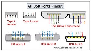
This article explains the pin layouts for different USB ports or connectors types — Type A/B, Mini, Micro, USB3 and Type-C — so you can identify and wire them correctly.
Table of Contents
The USB pinout can be divided into two parts: USB Connector and port pinout. The connector here refers to the device that goes into the USB port. For example, a wired Mouse is connected to the laptop by inserting its connector into the USB port.
Hence, the terms Male version for the Connector and Female version for the USB port are tossed.
USB type A and type B pinout(male and female)
USB Type-A is used to make a connection with a PC while Type B is used to connect smaller peripherals. In other words, Type A is a downstream connector, while Type B is an upstream connector.
The USB type A is rectangular, while type B has a square-like shape. Both of them have 4 pins. The figure below shows the Pin layout of the Male and Female versions of both USBs.
Note: The Female version is actually the USB connector (Connector of a Keyboard for example) and the male version is the USB port( Ports on your laptop for example)

Both these USB types differ in purpose and shape, but their pin connections are the same. Pin 1 is dedicated to the supply and pin 4 is for ground connection. Even pin 2 and 3 take the data input from both these types.
The female port has the PINs in descending order, starting from the right-hand side, while the male connector has them in the reverse order. The table below shows the pinout of both USBs.
| Pin | Signal | Colour | Description |
| 1 | Vcc | Red | +5V |
| 2 | D- | White | Data- |
| 3 | D+ | Green | Data+ |
| 4 | GND | Black | Ground |
Note: Since the USB port and USB connector pinout are exactly the same but in opposite direction, the USB pinouts shown below are of connectors only.
USB mini A and mini B
USB Mini was the first improvised version of the standard connectors. This version was launched for both Type A and Type B.
It’s a smaller version of Type A and B, which were extensively used with old mobile phones. The Mini B connector is more popular than the Mini A. The figure below shows the pin diagram of USB Mini B.

USB Mini B is thinner and more compact than Mini A. Hence, it is used for PDAs, digital cameras, etc. Another significant development introduced with Type Mini is that it has an additional pin to support On-the-GO (OTG) connection. Thus, it has 5 pins. The pin connections are given in the table below.
| Pin | Signal | Colour | Description |
| 1 | Vcc | Red | +5V |
| 2 | D- | White | Data- |
| 3 | D+ | Green | Data+ |
| 4 | ID | N/A | USB OTG ID |
| 5 | GND | Black | Ground |
USB micro A and micro B

USB Micro is thinner and gives a higher data transfer speed than the USB Mini. It is often used for charging portable devices and comes in two shapes. Micro A is rectangular whereas Type Micro B has a camper shape.
The USB Micro also has 5 pins similar to that of the USB Mini, where the additional pin supports OTG connectivity. The table below shows the pinout of Micro-A and B.
| Pin | Signal | Colour | Description |
| 1 | Vcc | Red | +5V |
| 2 | D- | White | Data- |
| 3 | D+ | Green | Data+ |
| 4 | ID | N/A | USB OTG ID |
| 5 | GND | Black | Ground |
USB standard 3
USB Standard 3 is widely known as the SuperSpeed Mode that brought a revolution in USB manufacturing. The models used in the third generation are highly advanced, offer faster data speed, have a compact design, and are easy to handle.
Features of USB standard 3
The standard 3 models are accepted globally due to the following benefits:
- It is capable of transferring data with a speed of 5Gbps and above.
- Since separate unidirectional paths are used to transmit and receive data, it has a larger bandwidth.
- With predefined power management states, it offers better power management.
- It allows the devices to notify about the data transfer, thereby improving the bus usage.
Standard 3 connectors come in the same physical configuration but with an additional 5 pins to handle these advancements. It includes additional ground and dedicated pins for transmission and reception which are called super-speed connections. (learn more)
The pinout diagrams of the superspeed versions of different USB types are described in the following section.
USB type A 3.0 and type B 3.0
As discussed above, the normal Type A and Type B connectors have 4 pins. But the superspeed versions of Standard 3 have 9 pins which are visible in the figure below.

The table below shows the pinout of the superspeed versions.
| Pin | Colour | Signal | Description |
| 1 | Red | Vcc | +5 DC |
| 2 | White | D- | Data – |
| 3 | Green | D+ | Data + |
| 4 | Black | GND | Ground |
| 5 | Blue | StdB_SSRX- | Superspeed Transmit- |
| 6 | Yellow | StdB_SSRX+ | Superspeed Transmit+ |
| 7 | N/A | GND_Drain | Ground Signal Return |
| 8 | Purple | StdB_SSTX- | Superspeed Receive- |
| 9 | Orange | StdB_SSTX+ | Superspeed Receive+ |
Micro B 3.0

The superspeed version of Micro USB was introduced to Type B. Apart from the existing structure, the five additional pins are placed as an extension. Thus, it has a wider structure. The pinout of the Superspeed Micro B USB connector is given in the table below.
| Pin | Colour | Signal | Description |
| 1 | Red | Vcc | +5 DC |
| 2 | White | D- | Data – |
| 3 | Green | D+ | Data + |
| 4 | N/A | ID | OTG ID |
| 5 | Black | GND | Ground |
| 6 | Blue | StdB_SSRX- | Superspeed Transmit- |
| 7 | Yellow | StdB_SSRX+ | Superspeed Transmit+ |
| 8 | N/A | GND_Drain | Ground Signal Return |
| 9 | Purple | StdB_SSTX- | Superspeed Receive- |
| 10 | Orange | StdB_SSTX+ | Superspeed Receive+ |
USB type c 3.0
Type C has been the game-changer among all the USB types. It supports data transmission as well as power delivery. Thus, it has become a universal connector for modern devices.

The major attraction of Type C USB is that it is flippable. The figure above shows the pin connections with their corresponding color. The pin connections at the top and bottom are similar, so we don’t have to bother to insert the connector in the correct direction.
It has an incredible data transfer speed of up to 5Gbps and very high power delivery, and in some devices can replace legacy ports like Ethernet or DisplayPort. The connection description is given in the table below.
| Pin | Description | Pin | Description |
| A1 | Ground | B12 | Ground |
| A2 | Superspeed differential pair 1, TX, positive | B11 | Superspeed differential pair 2, RX, positive |
| A3 | Superspeed differential pair 1, TX, negative | B10 | Superspeed differential pair 2, RX, negative |
| A4 | Bus power | B9 | Bus power |
| A5 | Configuration channel | B8 | Side Band Use (SBU) |
| A6 | Differential pair 1, positive | B7 | Differential pair 2, negative |
| A7 | Differential pair 1, negative | B6 | Differential pair 2, positive |
| A8 | Side Band Use (SBU) | B5 | Configuration channel |
| A9 | Bus power | B4 | Bus power |
| A10 | Superspeed differential pair 4, RX, negative | B3 | Superspeed differential pair 3, TX, negative |
| A11 | Superspeed differential pair 4, RX, positive | B2 | Superspeed differential pair 3, TX, positive |
| A12 | Ground | B1 | Ground |
Great knowledge about USB…
Thank you
Glad to be of help.
Great basic explanation without getting too deep in the protocals.