A digital spirit level measures roll and pitch angles in real time using an accelerometer or gyroscope. In this project, we will use an ESP32 microcontroller and an ADXL345 sensor to make it.
Watch the video tutorial below:
Table of Contents
How does this spirit level work?
The ADXL345 accelerometer measures real-time roll and pitch angles. It also detects orientation changes and provides this data to the ESP32.
The ESP32 uses this data and displays the angles on an OLED screen, along with a moving circle to graphically indicate the object’s orientation. This smart bubble level simplifies tasks like object leveling by providing accurate angle measurements.
Components required
- ESP32
- ADXL345 accelerometer sensor
- 0.96-inch OLED display
- Breadboard
Introduction to ADXL345 accelerometer sensor
The ADXL345 is a flexible 3-axis accelerometer sensor that measures acceleration in three dimensions precisely. It has high resolution (up to 13-bit), a wide range of sensitivity options, and low power consumption, making it perfect for motion, tilt, and vibration detection in a variety of applications.
This sensor can communicate through I2C or SPI so it is suitable for use in microcontroller-based projects.
Pinout of ADXL345
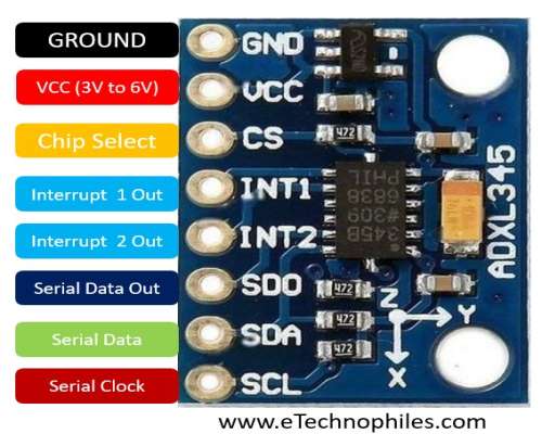
The pin diagram of the ADXL345 sensor is given below.

| Pin name | Pin description |
| GND | Ground pin |
| VCC | Power supply (3V to 6V) |
| CS | Chip select pin |
| INT1 | Interrupt 1 output pin |
| INT2 | Interrupt 2 output pin |
| SDO | Serial data output pin |
| SDA | Serial data input & output |
| SDL | Serial communication clock |
Circuit diagram
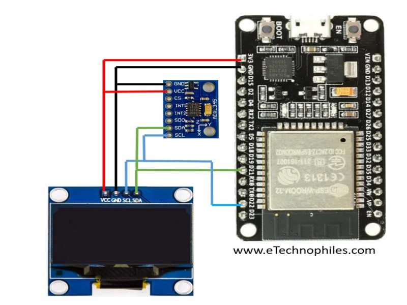
The figure below shows the circuit diagram of the project.

| OLED Pin | ESP32 Pin |
| VCC | 3V3 Pin |
| GND | GND of ESP32 |
| SDA | GPIO21 |
| SCL | GPIO22 |
| ADXL Pin | ESP32 Pin |
| VCC | 3V3 Pin |
| GND | GND of ESP32 |
| SDA | GPIO21 |
| SCL | GPIO22 |
Physical connections
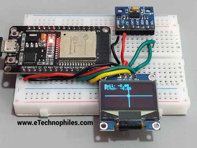
The project is assembled on a breadboard, this is how it looks:

Program
Copy and paste the program given below to your Arduino IDE. Before uploading the program, select the correct board and port.
#include <Wire.h>
#include <Adafruit_GFX.h>
#include <Adafruit_SSD1306.h>
#include <Adafruit_ADXL345_U.h>

#define SCREEN_WIDTH 128
#define SCREEN_HEIGHT 64
#define OLED_RESET -1

Adafruit_SSD1306 display(SCREEN_WIDTH, SCREEN_HEIGHT, &Wire, OLED_RESET);
Adafruit_ADXL345_Unified accelerometer = Adafruit_ADXL345_Unified(12345);

void setup() {
  Serial.begin(115200);

  if (!accelerometer.begin()) {
    Serial.println("Could not find a valid ADXL345 sensor, check wiring!");
    while (1);
  }

  if (!display.begin(SSD1306_SWITCHCAPVCC, 0x3C)) {
    Serial.println(F("SSD1306 allocation failed"));
    for (;;) ;
  }

  display.clearDisplay();
  display.setTextSize(1);
  display.setTextColor(SSD1306_WHITE);
  display.setCursor(0, 0);
  display.println("Spirit Level");
  display.display();
  delay(2000);
}

void loop() {
  sensors_event_t event;
  accelerometer.getEvent(&event);

  float roll = atan2(event.acceleration.x, event.acceleration.z) * 180.0 / PI;
  float pitch = atan2(event.acceleration.y, event.acceleration.z) * 180.0 / PI;

  display.clearDisplay();
  display.setTextSize(1);
  display.setTextColor(SSD1306_WHITE);
  display.setCursor(0, 0);
  display.print("Roll: ");
  display.println(roll);
  display.print("Pitch: ");
  display.println(pitch);

  display.drawLine(0, SCREEN_HEIGHT / 2, SCREEN_WIDTH, SCREEN_HEIGHT / 2, SSD1306_WHITE);
  display.drawLine(SCREEN_WIDTH / 2, 0, SCREEN_WIDTH / 2, SCREEN_HEIGHT, SSD1306_WHITE);

  int bubbleX = map(roll, -90, 90, 0, SCREEN_WIDTH);
  int bubbleY = map(pitch, -90, 90, 0, SCREEN_HEIGHT);
  display.drawCircle(bubbleX, bubbleY, 3, SSD1306_WHITE);

  display.display();
  delay(100);
}
Program explanation
Library includes:
#include <Wire.h>
#include <Adafruit_GFX.h>
#include <Adafruit_SSD1306.h>
#include <Adafruit_ADXL345_U.h>
The code includes several libraries required for the project:
Wire.h: I2C communication library.
Adafruit_GFX.h: Graphics library for drawing on the display.
Adafruit_SSD1306.h: OLED display control library.
Adafruit_ADXL345_U.h: Library for interfacing with the ADXL345 accelerometer.
Constant definitions:
#define SCREEN_WIDTH 128
#define SCREEN_HEIGHT 64
#define OLED_RESET -1
Constants are defined for the width, height, and reset pin of the OLED display. These values are used to configure the display.
Display and accelerometer object initialization:
Adafruit_SSD1306 display(SCREEN_WIDTH, SCREEN_HEIGHT, &Wire, OLED_RESET);
Adafruit_ADXL345_Unified accelerometer = Adafruit_ADXL345_Unified(12345);
Instances of the Adafruit_SSD1306 and Adafruit_ADXL345_Unified classes are generated. The display object is used to control the OLED display, while the accelerometer object is used to communicate with the ADXL345 accelerometer.
Setup function:
void setup() {
  Serial.begin(115200);

  if (!accelerometer.begin()) {
    Serial.println("Could not find a valid ADXL345 sensor, check wiring!");
    while (1);
  }

  if (!display.begin(SSD1306_SWITCHCAPVCC, 0x3C)) {
    Serial.println(F("SSD1306 allocation failed"));
    for (;;) ;
  }

  display.clearDisplay();
  display.setTextSize(1);
  display.setTextColor(SSD1306_WHITE);
  display.setCursor(0, 0);
  display.println("Spirit Level");
  display.display();
  delay(2000);
}- For debugging purposes, serial communication is enabled.
- The code checks if the accelerometer is detected and ready to use. If not, it prints an error message and enters an infinite loop.
- The OLED display is initialized, and if initialization fails, it enters an infinite loop.
- The OLED display gets cleared, and some initial text (“Spirit Level”) is displayed. Then, there’s a 2-second delay.
Loop function:
void loop() {
  sensors_event_t event;
  accelerometer.getEvent(&event);

  float roll = atan2(event.acceleration.x, event.acceleration.z) * 180.0 / PI;
  float pitch = atan2(event.acceleration.y, event.acceleration.z) * 180.0 / PI;

  display.clearDisplay();
  display.setTextSize(1);
  display.setTextColor(SSD1306_WHITE);
  display.setCursor(0, 0);
  display.print("Roll: ");
  display.println(roll);
  display.print("Pitch: ");
  display.println(pitch);

  display.drawLine(0, SCREEN_HEIGHT / 2, SCREEN_WIDTH, SCREEN_HEIGHT / 2, SSD1306_WHITE);
  display.drawLine(SCREEN_WIDTH / 2, 0, SCREEN_WIDTH / 2, SCREEN_HEIGHT, SSD1306_WHITE);

  int bubbleX = map(roll, -90, 90, 0, SCREEN_WIDTH);
  int bubbleY = map(pitch, -90, 90, 0, SCREEN_HEIGHT);
  display.drawCircle(bubbleX, bubbleY, 3, SSD1306_WHITE);

  display.display();
  delay(100);
}- The loop reads accelerometer data continuously.
- It computes the roll and pitch angles based on accelerometer data using trigonometric functions.
- The OLED display is cleared, and the roll and pitch values are displayed.
- On the display, horizontal and vertical reference lines are drawn.
- Based on the roll and pitch angles, a tiny circle (bubble) showing the orientation is drawn on the display.
- The display is updated, and there’s a 100-millisecond delay before the loop repeats.
Conclusion
In this project, we used an ESP32, an ADXL345 accelerometer, and an OLED display and made a digital spirit level. Whether you’re fixing a picture or playing with a robot, this digital spirit level is like a smart, modern bubble level. It helps you make things straight and balanced easily.
