Last updated on June 6th, 2024 at 02:28 pm
In this article, we will discuss how to make a WiFi strength checker using an ESP32 microcontroller and an OLED display. It allows users to measure the strength of their Wi-Fi network’s signal. The strength can be analyzed in the dBm unit.
The project has useful advantages, such as assisting users in choosing the best router location in their home or workplace. It also assists in resolving connectivity problems by giving immediate feedback on the WiFi signal’s quality.
Table of Contents
Watch the video tutorial below:
Components required
- ESP32 microcontroller
- 0.96 Inch I2C/IIC 4-Pin OLED display module
Introduction to OLED display
OLED displays come in different sizes (128×64, 128×32, etc.) and colors (e.g. white, blue, and dual-color OLEDs). Some feature an SPI interface, while other OLED displays have an I2C interface. Also an OLED display, unlike a character LCD, does not require a backlight because it generates its light.
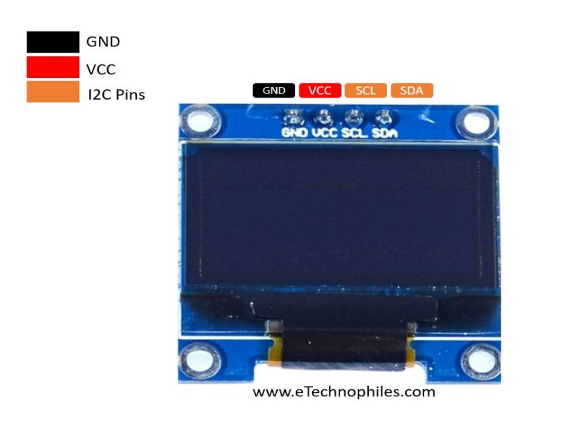
In this project, we used a 0.96” I2C OLED display. The figure below shows its pinout.

| Pin | Description |
|---|---|
| GND | Ground |
| VCC | Supply Pin |
| SCL | Serial Clock Pin |
| SDA | Serial Data Pin |
Circuit diagram
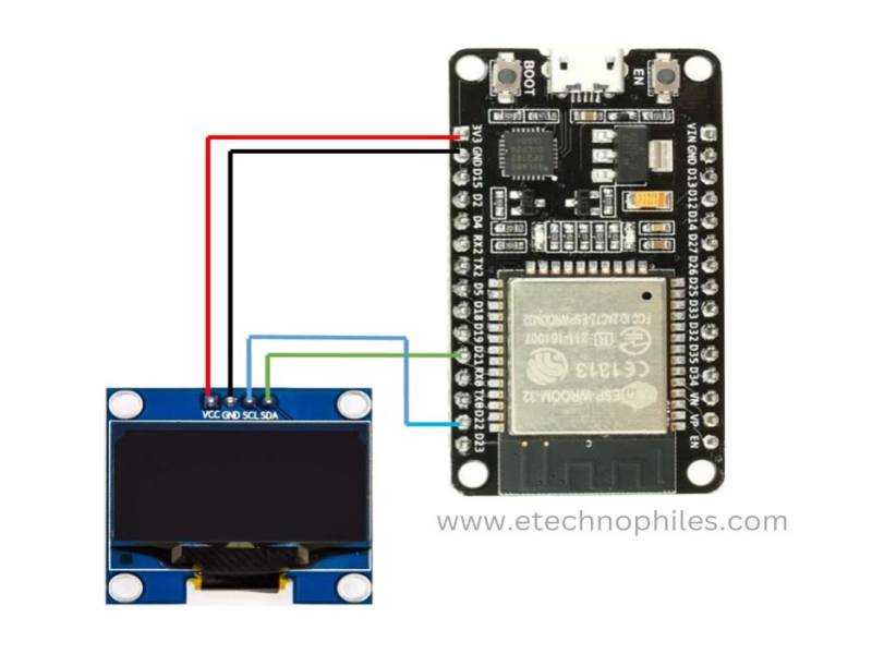
The circuit diagram of the project is shown below.

Connections
There are a total of four pins on OLED. Connect them to ESP32 according to the table given below:
| OLED Pin | ESP32 Pin |
| VCC | 3V3 Pin |
| GND | GND of ESP32 |
| SDA | GPIO21 |
| SCL | GPIO22 |
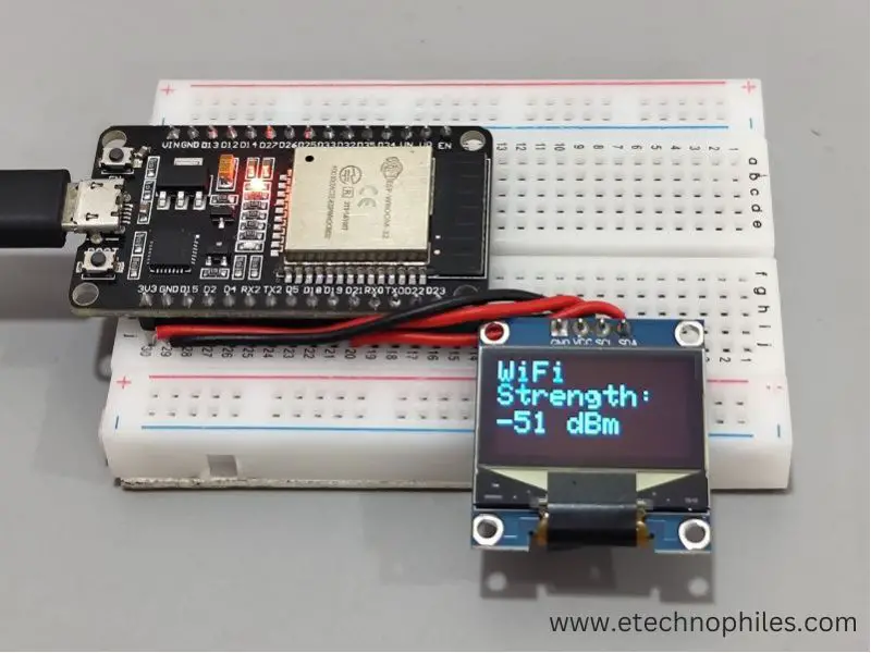
We used a breadboard and connected the OLED with ESP32, as shown below.

Program
Copy and paste the program given below to your Arduino IDE. Before uploading the program, select the correct board and port.
#include <Wire.h>
#include <Adafruit_GFX.h>
#include <Adafruit_SSD1306.h>
#include <WiFi.h>

#define OLED_ADDR 0x3C
#define OLED_SDA 21
#define OLED_SCL 22
#define OLED_RST 16
#define SCREEN_WIDTH 128
#define SCREEN_HEIGHT 64

Adafruit_SSD1306 display(SCREEN_WIDTH, SCREEN_HEIGHT, &Wire, OLED_RST);

void setup() {
  Serial.begin(115200);
  delay(100);

  // Initialize OLED display
  display.begin(SSD1306_SWITCHCAPVCC, OLED_ADDR);
  display.clearDisplay();
  display.setTextColor(WHITE);

  // Connect to WiFi
  WiFi.begin("SSID", "Password");

  while (WiFi.status() != WL_CONNECTED) {
    delay(1000);
    Serial.println("Connecting to WiFi...");
  }

  Serial.println("Connected to WiFi");
}

void loop() {
  int32_t rssi = WiFi.RSSI();

  display.clearDisplay();
  display.setTextSize(2);
  display.setCursor(0, 0);
  display.print("WiFi      Strength:");
  display.setTextSize(2);
  display.setCursor(0, 35);
  display.print(rssi);
  display.setTextSize(2);
  //display.setCursor(0, 50);
  display.print(" dBm");
  display.display();

  delay(1000);
}
Make sure to replace the SSID and PASSWORD with the credentials of your Wifi network
Program explanation
Include libraries: The program starts by including several libraries needed for various functionalities:
- wire.h: Library for I2C communication.
Adafruit_GFX.h: Graphics library for the OLED display.Adafruit_SSD1306.h: OLED display driver library.WiFi.h: Library for WiFi connection handling.
Define constants: We need to define several constants to specify the pins and display dimensions.
- OLED_ADDR, OLED_SDA, OLED_SCL, OLED_RST: This is for the I2C address and pins of an OLED display.
- SCREEN_WIDTH and SCREEN_HIGHT: This is for screen dimensions of OLED display
Initialize OLED display: The I2C pins and provided screen specifications are used to generate the Adafruit_SSD1306 object display. The screen is set to blank, and the font color is set to white.
Setup function:
- For debugging purposes, serial connectivity is started.
- The OLED display is set up, and any previous content is erased.
- The ESP32 is configured to connect to a WiFi network with SSID and password.
- The ESP32 waits until it successfully connects to WiFi and prints a message when connected.
Loop function: The steps listed below are continuously carried out by the program inside the loop function:
- Firstly, it retrieves the WiFi signal strength (RSSI) using the ‘WiFi.RSSI()’ function and stores it in ‘rssi’ variable.
- The OLED display is cleared, and the text size is set to 2.
- Then on display, WiFi strength in dBm gets printed.
- The cycle is repeated after a one-second delay.
Conclusion
In conclusion, this project demonstrates how to create a simple WiFi signal strength monitor using an ESP32 board, and an OLED display. This project can be useful for various applications, such as monitoring the quality of a WiFi connection in a specific location or debugging WiFi-related issues in a project.
It shows the WiFi signal strength in a simple visual representation, allowing users to rapidly assess the network’s performance.
