Last updated on February 11th, 2025 at 10:55 am
ESP32 is an upgraded version of the famous ESP8266 module developed by Espressif Systems. The newly added features like an additional core, faster Wi-Fi, and, dual-mode Bluetooth (4.2 and BLE) made it preferable for IoT applications.
Today, many enthusiasts prefer this tiny yet powerful SoC (System on Chip) over other development boards. This article presents some new ESP32 projects for enthusiasts that they can try this year.
ESP32 features
Before we start discussing ESP32 projects, let us see some technical details of the board.
| Processor | Tensilica Xtensa 32-bit LX6 microprocessor |
| Number of cores | 2 |
| Clock frequency | up to 240 MHz |
| Performance | up to 600 DMIPS |
| Wi-Fi | 802.11 b/g/n/e/i (802.11n @ 2.4 GHz up to 150 Mbit/s) |
| Bluetooth | v4.2 BR/EDR and Bluetooth Low Energy (BLE) |
| ROM | 448 KB – For booting and core functions |
| SRAM | 520 KB – For data and instruction |
| Flash | Extern QSPI – 16MB |
| GPIO | 22 |
| DAC | 2 |
| ADC | 18 |
Table of Contents
Smart front door light
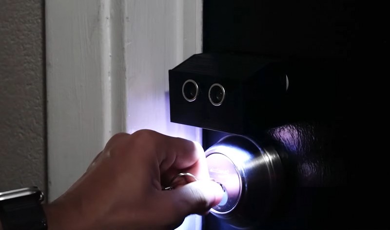
If you’ve ever struggled to find the keyhole of your front door in the dark and had to use your phone’s flashlight, this project offers a simple solution. The maker designed a front door light that sits above the doorknob.
It uses an ultrasonic sensor to detect when someone approaches, automatically lighting up a string of neopixels to illuminate the area around the knob. This makes finding the keyhole in the dark quick and easy, without any extra hassle.
To make it portable, the device is powered by a lithium-ion battery and included a charging circuit, all housed in a custom 3D-printed frame.
LED matrix clock
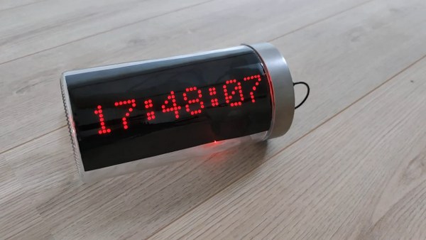
Our first project is an LED matrix clock housed inside an old plastic jar. It uses an 8×8 MAX7219 LED Matrix as the display. Apart from displaying the date and time, it also shows the temperature and humidity of the ambient. For this, it uses a DHT11 sensor.
It also uses a KY-018 Photoresistor Module to measure the light intensity. Its resistance is inversely proportional to the outside light. So, if the light intensity is higher, its resistance will be low and vice-versa.
One part of the jar is covered with a solar film for the display, while the other side is open for the visibility of the components.
ESP32-OLED scrolling message display
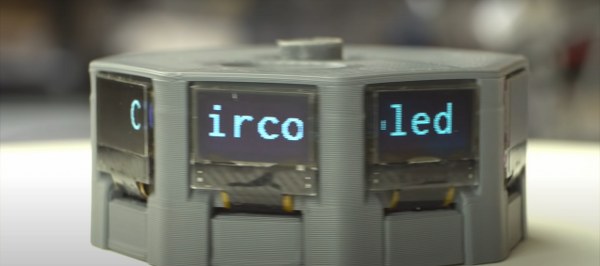
For displaying a message, how many displays will you choose? One, or a maximum of two, right? But, in this project, Maker Moekoe has selected eight OLEDs to display a single message. Isn’t it amazing?
The OLEDs are arranged in a circle to give the text a scrolling effect. These displays are placed around a PCB and controlled by a single ESP32.
The Blynk app lets you display a message as well as alter the speed of the moving text. Moreover, it can show data like battery state, temperature, and more.
IoT weather station
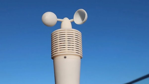
What is the easiest way to get an update on the weather stats? A smartphone or a smartwatch, right? But is the data accurate enough? Does it accurately give the weather conditions around your house? Because this project can do that.
This wireless outdoor weather station takes temperature, humidity, barometric pressure, light, and wind speed readings and regularly updates them to a cloud.
Now, all you need is an active internet connection, and you can access these readings through a Thingspeak dashboard. Whether it be your computer, mobile, or tablet, you can access the exact weather stats around your house, anytime.
Water level controller
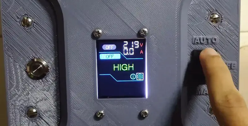
Next, we have a wireless water level controller. It uses the ESP-NOW protocol to transmit data, with a range of up to 500 meters in a clear line of sight. The controller is designed with built-in protections against high or low voltage, overload, and dry run conditions.
It features two float switches to monitor the water level in the tank and offers three controlling modes: auto, off, and manual. All data, including voltage, current, power, and transmitter battery voltage, is displayed on the TFT screen.
ESP32 & MPU-9250: 3D orientation visualisation
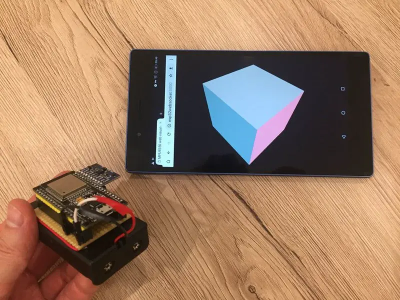
MPU-9250 is a nine-axis Motion Processing Unit suitable for any motion-tracking device. It is a combination of two chips:
- MPU-6500
- AK8963
The MPU-6500 contains a 3-axis gyroscope, a 3-axis accelerometer, and an onboard DMP (Digital Motion Processor), while the AK8963 is a 3-axis digital compass.
A DMP can perform complex MotionFusion algorithms. And can read orientation data in the form of Euler angles or quaternions directly from the chip.
So, this project visualizes a 3D cube orientation using an MPU-9250. An ESP32 hosts the webpage and visualizes the cube in real time.
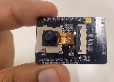
ESP32-CAM SmartCam
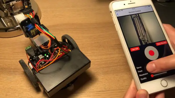
The ESP32-based video surveillance robot is one of the handy projects in the ESP32 projects list. You can either mount this camera on a wall or attach it to an RC car for a portable version. The i-Robbie app lets you control all the movements of the camera.
With its pan and tilt advantage, its range gets increased beyond the line of sight. The servo motors can move the camera in any direction as per the instructions. The portable version of the robot comes with a more exciting feature like night-mode vision.
BLE macro keyboard

This shortcut keypad is designed to save you time and boost productivity while working on your laptop or PC. It features 10 keys and a rotary encoder, making it easy to access commands or functions quickly.
A small OLED screen at the top displays essential information, such as the active mode and various LED glow patterns. The PCB is compact, with carefully arranged space for the keys and rotary encoder. An enclosure, 3D-printed using PLA filament, protects the electronics.
The rotary encoder adds versatility by allowing volume control, scrolling, or even zooming, depending on how you configure it.
Small quadruped robot
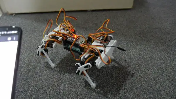
A quadruped robot is a four-legged robot that follows the gait patterns of quadruped animals. The robot dog designed here requires an ESP32 and an Arduino module. Using a mobile phone and a Wi-Fi connection, you can control the movements of the robot dog.
The complete body of the robot dog is 3D printed. It can walk easily on most surfaces, even the elevated ones. The configurable gait sequence lets you teach some more tricks to this robot dog.
DIY BLE Gamepad
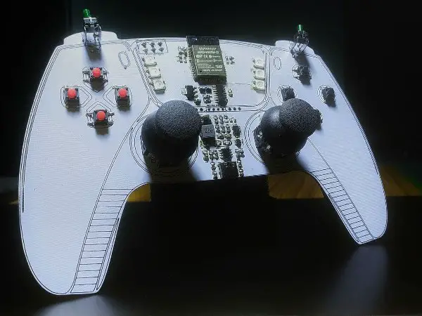
After some techy ESP32 projects, let us see a unique homemade gamepad.
Most gaming boards use an Arduino because it supports HID (human interface devices). HID provides an interface between the user and the computers.
But, as we know, an ESP32 is not equipped with such an aspect. Hence, to operate this gamepad using an ESP32, we will use the wireless feature of ESP32. The gamepad consists of:
- Two analog joysticks
- Two trigger buttons
- two D-pads
- six addressable LEDs
- one I2C port
- one 3way switch
The gamepad runs on two 18650 Li-Ion cells, which gives ample playtime on a single charge.
DIY motor driver PCB

A 6-channel motor driver circuit was built using six different ICs, each capable of handling 1-2 amps of current. An ESP32 Mini was used to control the ICs, which were soldered onto the board along with the other components.
While these ICs offer a wide range of features, the basic functions focused on were motor speed control and direction change. The program runs the motor for three seconds in one direction, pauses, and then reverses.
The motor driver circuit can not only control small motors but can also handle heavy motors. Additionally, by utilizing two separate coils, these ICs can easily control stepper motors.
VGA Arcade Games and Joystick
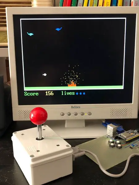
Are you a die-hard fan of the Arcade games? To bring back the joy of arcade gaming, we have selected an ESP32-based Arcade game project. With the arcade controller joystick, you can play four games using this setup.
These are Tetris, Snake, Breakout, and Bomber. Despite a low resolution of 320×200 pixels, it gives a remarkable game-playing experience.
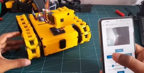
BLE RC CAR project

This BLE-controlled RC car utilizes Bluetooth Low Energy (BLE) for seamless communication between the car and the mobile app. The app, developed using Flutter, provides a clean and user-friendly interface for easy control.
The RC car is powered by a 12V lithium-ion battery, with the L298N motor driver used to control the motors. The 5V output from the L298N powers the ESP32 microcontroller.
The ESP32’s Motor Control PWM is used to adjust the speed of the DC motors, allowing precise control over the car’s movement. For steering, the ESP32 Servo Library was implemented, enhancing the system’s overall efficiency.
Ghosty and Skully Halloween Robots
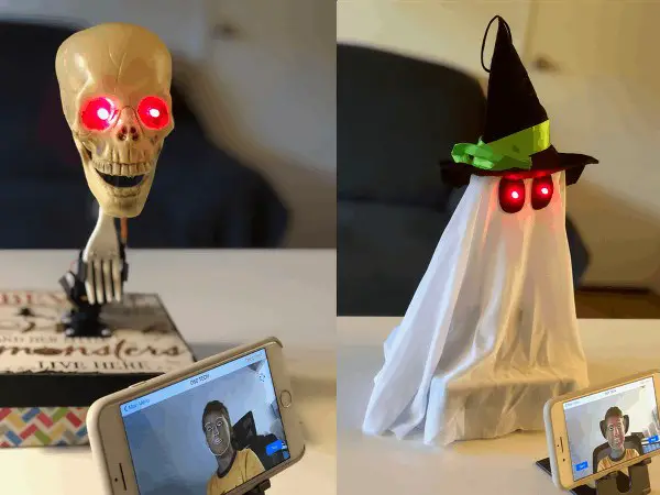
This Halloween, scare your friends with two new homemade robots, Ghosty and Skully. The robots track your face and give a smile back at you if you smile at them. Scary, right?
All you need are some cheap Halloween decorations and an iRobbie app. The iRobbie app lets you control Arduino, ESP8266, or ESP32-CAM robots with your iPhone. The app gives you numerous features like object tracker, face and smile recognition, object finder, voice control, remote control, video surveillance, etc.
The app captures and processes the video and sends X, and Y coordinates, and smile status to the Arduino via the HM-10 Bluetooth module. The robots respond to the input by following your face and giving a scary laugh.
4WD car
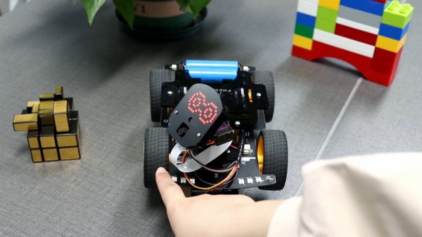
Our next project is a tiny, fast, and versatile robot car. It uses two photodiodes on either side and a line-tracking module in the middle. With this, it can follow a line, track any object, avoid obstacles, and much more. It has multi-colored LEDs around it, which gives it a sparkling look in the dark.
Moreover, you can also control this car like any other RC car using an IR remote. It captures real-time video and transmits it to the Bluetooth-controlled app on your smartphone.
Voice Assistant
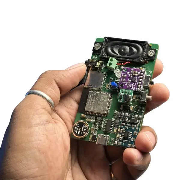
This portable voice assistant has been developed to respond to any question with the press of a button. Powered by Gemini AI and running on a single ESP32 module, the device can translate queries into different languages, solve math problems, and perform various other tasks.
The IoT project features a custom PCB with a battery management system, voltage regulator, amplifier, microphone, and an SD card for storing audio. A key feature is the automatic programming function, which removes the need to press the boot button when uploading code.
Additionally, the device includes a speaker, an RGB LED as a status indicator, and a headphone jack for private audio output. A battery level monitor is integrated to alert the user when the battery is low.
E-paper photo frame
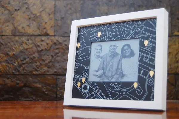
Pictures are the best way to recall good memories, Right? And what would be better than a photo frame that displays your favorite moments?
The project uses an E-Ink display. These displays mimic the appearance of ink on paper. They don’t require a continuous power supply to display the data on the screen. Hence, it can display the last content for long hours even after the power is off.
The concept of the project is to display an image taken at a particular location. For this, the PCB consists of a silkscreen layer that shows the layout of a map. The copper touchpad looks like a location symbol. So, as you press the capacitive touchpad, an image gets displayed on the e-paper.
Excavator on breadboard
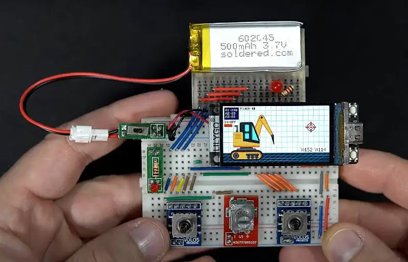
This may look like a simple animation, but it’s much more. An excavator has been designed to light up an LED when the tip points at a target, providing a clever way to activate the LEDs.
The excavator was created using only lines, circles, triangles, and squares. Instead of using multiple push buttons or a bulky joystick, a compact joystick module with five built-in buttons was used, keeping the setup neat and clean on the breadboard.
To control the excavator, eight push buttons are used for up, down, left, and right movements, while the speed can be adjusted with a potentiometer. Each segment has its own angle, and moving one affects the others. The code calculates the positions of these segments for precise control.
Simple AI robot

If you are looking for some basic ESP32 projects for image processing, you must start with this one. This project will guide you in building a simple robot that can detect and track objects.
You can control the robot using a smartphone or run it in an autonomous mode. Moreover, the requirements for this project are not much. All you need is:
- 1:120 DC geared motors x2
- ESP32-CAM module
- L298N motor driver
- Wheels x2
- Ball castor wheel x1
- Some ice cream sticks
- Cardboard
- Power bank
And that’s it. You now have your first AI robot in front of you.
Digital roulette table

Have you ever thought about building your own roulette table? A digital roulette game has been created, perfect for family game night. The project uses an ESP32, an audio board, LED strips, and a few buttons. The components are mounted on a simple PCB and housed in a custom casing with cutouts for the push button, speaker, and LEDs.
The code controls the LED animations and audio, simulating a spinning roulette ball that slows down to a random number, creating an immersive and entertaining experience for players.
GPS tracker
GPS (Global Positioning System) is a satellite-based navigation system to determine the precise location of an object. It uses a technique (called trilateration) to calculate the position, velocity, and elevation of the target.
This project uses an AI-Thinker A7 module as the GPS module. To determine any location, connect the device with the Blynk app. Once the connection gets established, you can request a random position or the GPS position from the tracker.
MS Paint on ESP32
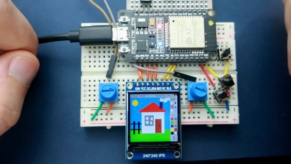
All the above ESP32 projects either control something or run something. But this project lets you paint. Yes, you heard it right. It uses an ESP32 board and a 240×240 TFT display.
Using the two potentiometers on either side of the display, you can move the cursor in your available workspace.
One potentiometer controls the X-axis(horizontal) movement while the other controls the Y-axis(vertical) movement. It also has four pushbuttons, three on the side and one at the top.
The pushbuttons on the side select a shape and color to draw in the workspace, while the top one undos the last drawn object on the workspace.
Portable Wireless touch remote
ESP32 comes with ten capacitive touch GPIOs. These pins can detect electrical signals. For example, it can respond to human touch and give output depending on the electrical charge on the finger.
Hence, you can use this feature to make ESP32 a mouse for your PC, a remote for your smartphone camera, or a switch to use as a home automation device.
Cafeino: The Barista Robot
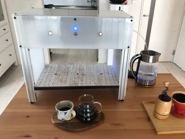
If you are a coffee lover and want freshly brewed coffee anytime you want, then try the Barista robot. This robot makes high-end artisanal coffee (coffee made traditionally by a skilled person). Now, you might think, how a machine can do that? Right?
So, the answer is that Cafeino mimics the hand-pouring technique of a skilled human barista. It has three brewing stations, and you can customize the brewing recipes like:
- Customizing the brewing and resting time
- Water quantity
- Hand pouring pattern used
- Or add any new brewing step
And all this, with just a web app. So, with the Barista robot, make a cup of freshly brewed coffee according to your taste.
Macro keypad
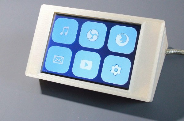
In computing, using hotkeys/ macros is a great way to save time and speed up the workflow. Now, whether it be video editing or playing games, these shortcuts are a must. But, if you look for a dedicated macro keypad for this on the web, you might change your mind as the cost associated with it is too high.
So, what can you do? Well, use this project, FreeTouchDeck, and save a fortune. All it uses is an ESP32 and a 3.5″ touch screen.
FreeTouchDesk allows you to customize menus, buttons, logos, and colors. You can even create buttons and upload them using the configurator (a web page hosted on ESP32).
Wi-Fi remote with TFT display
It is a tiny remote that uses an ESP32 Pico D4. The ultra-small size of ESP32 Pico D4 and low-energy consumption give it an additional advantage for low-spaced applications.
A TFT display (160×80 pixels) on the remote gives it a fabulous look. It becomes helpful to visualize GIFs, display temperature and humidity readings, etc.
The board has an additional feature of Wi-Fi and Bluetooth, which opens the door to many IoT applications.
Discord security camera
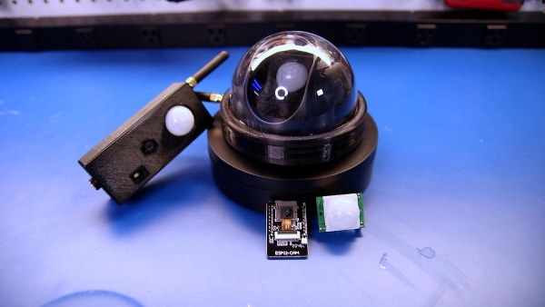
A PIR, or Passive Infrared Sensor, detects the infrared radiation in the surrounding environment. Inside it lies a pair of pyroelectric sensors. So, when someone enters the vicinity of the sensor, a signal difference occurs between the two pyroelectric sensors.
Thus, the sensor engages and notifies us by sending a message or triggering an alarm.
This security camera uses a PIR sensor and an ESP32-CAM. As the sensor detects any movement, The ESP32-CAM takes a picture of the intruder and posts it to a Discord channel.
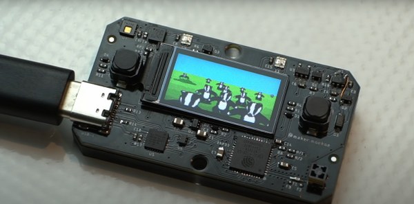
ESP32 Handheld Game console
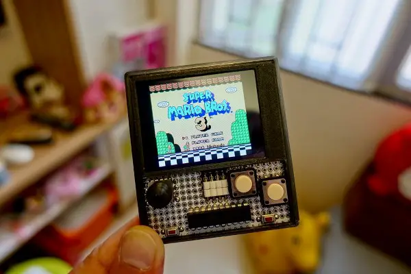
With a 2.4″ LCD and a 454262 LiPo battery, you can create a handheld game console that can run your favorite games. Although the resolution is 320×240, the experience it gives during the gameplay is fantastic.
The console requires 2 PCBs.
- One 0.4mm thick to support the display.
- One 1.2mm thick for an I2C gamepad.
So, which of the following ESP32 projects was your favorite? Tell us in the comment section below. If you have any excellent ESP32 projects with you, do share them with us.
Picoclick- ESP32-based IOT button
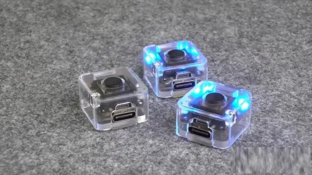
This is the smallest ESP32-based IoT button. It can be used for various home automation applications.
Consider this communication between two picoclicks. The one on the left acts as an IoT device and the other a receiver. It flashes a green LED if the second device is powered ON, otherwise, it flashes a red LED.
It can also be used for communicating with other devices like an OLED display, flight sensor, or a matrix display. Here it is used to send motion values from one picoclick to another and visualize them on an OLED display.
DIY E.D.I.T.H Smart Glasses
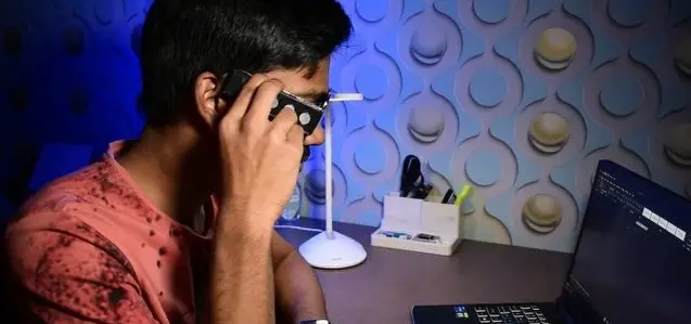
This project is a DIY version of the famous EDITH glasses. To solve the optics problem, OLED is placed parallel to the glass rim. A mirror is glued at a 60-degree angle that reflects the image from OLED.
A magnifying lens again reflects the image directly to the person’s eye. Touch sensors are provided on the PCB, to toggle between the apps. So, whether you want to look at the date, time, or any important notifications, you don’t have to pick up your phone for it. Just tap on the sensor, and you will get every detail on the tiny OLED display.
Smartwatch
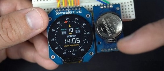
Watches are available in various shapes and designs. But making one using this round display would be interesting. It requires a real-time clock module to display the time. The complete display is a large sprite of resolution 240 by 240, so no flickering occurs in the display.
The gauge for seconds and the day moves continuously in the display. The red dot moves in the opposite direction just to confuse the person viewing the time.
This project is made on a breadboard, but by adding a couple of features to it on a custom PCB, this watch can turn into a pretty good smartwatch.
Multiple ESP32-CAM for Security Systems
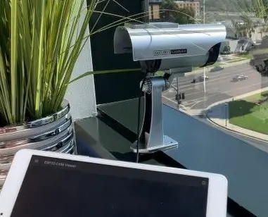
In this project, multiple ESP32 cameras and an old Android tablet are used to make a security camera. He installed the ESP32-CAM in a fake camera frame to make it more realistic.
Using an application, the output of all the cameras can be viewed on a single screen. Each camera has a unique IP address, which upon entering on the tablet lets you see the captured feed. Each video screen on the tablet is recorded separately and saved as an individual video clip.
3D printed Steam Train

Our next project is a 3D-printed model train setup. It is controlled via an ESP32-CAM wirelessly through a smartphone. The camera is mounted in the very front of the train, allowing one to watch a live stream of its progress about the tracks.
The eye-catching feature of the train is the smoke effect. For this, a small water atomizer is fitted in the train’s chimney, which makes the train look a little bit more authentic. It even has a lantern on the front, which gives it an amazing look while running at night.
Weather station
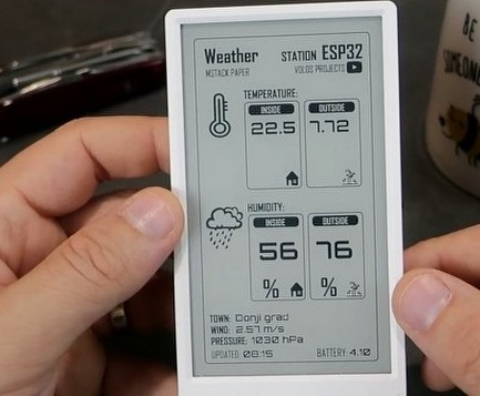
Want to keep track of the temperature conditions inside and outside of our house? Then use this E-paper display-based weather station. It has an SHT thirty sensor inside it that senses the temperature and humidity of the ambient.
To keep track of the weather conditions outside of the house, it relies on Open Weather API. The screen remains off most of the time. The weather data updates every 10 minutes, and the display holds this last refreshed image. In this way, this weather station maximizes the battery life.
Solar Power Monitoring System
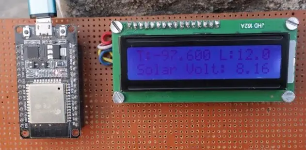
This solar power monitoring system keeps track of parameters like solar panel voltage, temperature, and light intensity. The real-time data can be viewed on an LCD screen.
But if you have an internet connection, you can view the data graphically on the ThingSpeak server from any part of the world. The data on the dashboard is updated every 15 seconds. The sensors are connected to the ADC pins, while the display is connected to the I2C pins of the ESP32.
To view the data on the dashboard you need to create a channel and generate an API key.
Smart Doorbell
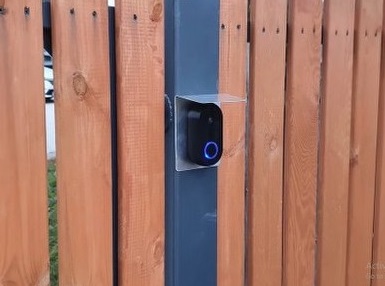
If you are watching a movie or playing video games at home and someone rings your doorbell, then we know how hard it is to check that. But with this smart doorbell, you will know who’s at the door without even getting up from your place.
When someone rings the doorbell, the camera captures the image of the person standing outside and sends it directly to your smartphone. From there you can either allow the person to let in or ignore them.
Door Lock System
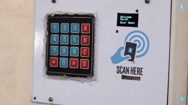
This two-in-one door lock system offers dual access options: RFID mode and pin code mode. Initiating the Pincode mode is as simple as pressing button A, and upon entering the correct pin, the door unlocks. To transition to the RFID mode, press button B.
Registered users can effortlessly gain access by scanning their RFID tag, while the system automatically logs the data onto a Google sheet. Exiting the premises is equally convenient, requiring only a simple gesture of hovering your hand over the proximity sensor, triggering the door to open.
ESP32 Internet Radio
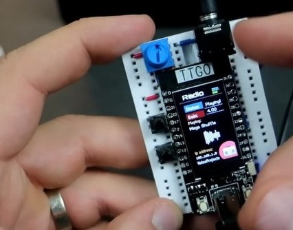
You might prefer listening to the radio using FM, but have ever tried it using the Internet? In this project, Volos used a TTGO T-display to tune into different radio stations.
The display connects to the internet and shows the IP address, gain, and the currently selected radio station. The radio stations can be changed via in-built push buttons, while the button on the side changes the brightness of the display. The breadboard version has a couple more extra features like the day and night modes for the display.
IoT Remote

This is a touchscreen remote through which you can control the status of various home appliances in your house. The interface of the display is simple, just an ON-OFF tap switch controlling a particular load.
To make this, you will need a TFT touchscreen display, an ESP32 module, a rechargeable battery, and a battery charging module.
You will require two authentication tokens in the code which is used to control the appliances of two different rooms.
Surveillance Robot
If you want to build a portable surveillance robot for your house then this is the project for you. The chassis for this robot is 3D printed. The tracks at the bottom provide better traction and let the robot run smoothly on rough terrain without getting stuck.
Two servo motors give the pan and tilt movement to the camera to capture the events in every direction. The movement of the robot is controlled via a smartphone on a local network.
It also shows the live stream from the camera and has separate controls for the camera and the movement of the track.
Gauge for ESP32 and TFT
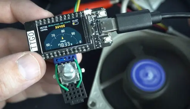
This project controls the speed of a fan using a TTGO display and a rotary encoder. The fan can be turned ON or OFF by pressing the rotary encoder. While turning the encoder in either direction controls the fan speed.
The RPM gauge on the display gives you precise speed control. By rotating the shaft of the encoder, pulses are produced which are counted by the microcontroller.
An optical mouse can also be used instead of a rotary encoder, which is an effective way to alter the speed.
ESP32 and ADS1115 ADC Voltmeter
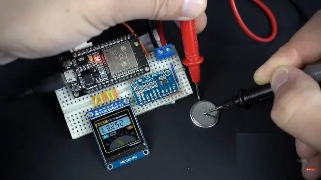
This project will teach you to build a voltmeter using an external ADC and an ESP32. Though most microcontrollers have an inbuilt analog-to-digital converter, they are not that precise. This module is a 16-bit ADC, that communicates with the ESP32 using the I2C protocol.
In the code, the voltage reference is set to 4.096 volts. This setup does not use a voltage divider circuit, hence measuring voltages greater than the reference voltage may damage the ADC or ESP32. But, using this you can get a precise voltage of batteries or other solar kits.
Bitcoin Price Ticker
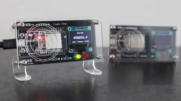
Keeping track of the crypto price becomes necessary when you regularly invest in it. This project can make that easy for you. This crypto ticker can display the price of any cryptocurrency as long as there is an API available for it in one of the exchanges.
It also displays the percentage change from the previous day’s closing price. The LED underneath the display also lights up, indicating whether the price has decreased or increased. The crypto price is updated every 15 minutes. This saves power as ESP32 switches to the deep sleep mode during the remaining time.
Play Video on a Tiny OLED Display
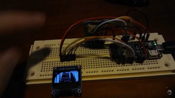
In this project, a 0.96-inch OLED display is used to watch movies. all the frames from the movie clips are collected and converted to the size of the OLED display. The file is stored on an SD card. The ESP32 reads this file and sends the corresponding frames to the OLED screen.
Musical Stepper Motors
You might have made music using various devices. But have you ever tried it using the motors? Yes, you can do this with the NEMA 17 stepper motors, as shown in this setup. This is achieved by stepping a motor forward and backward at a particular frequency.
By changing the step angle of the motor, the notes of a song can be matched. In this way, you can easily play a song using the stepper motors. The LED sets show the status of the motor, which is present at the left of the ESP32 module.
Social Media Follower Notifier
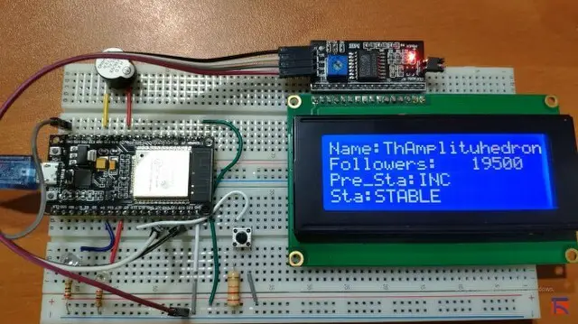
Do you want to keep track of the follower change for your various social media handles? Then you can start that with this simple project. It fetches the data from the social media account and gathers it on a web application.
When you gain or lose followers, a green or red LED lights up along with a buzzer sound. The track of the followers can be viewed on an LCD screen.
Well, this is just a prototype, you can modify this to view it on a big display. The notification message can be closed by pressing a push button provided on the setup.
Sending messages with the LoRa module
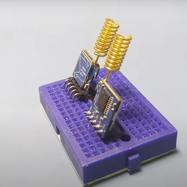
To send data between two points wirelessly you can either use a WiFi module or a Bluetooth module. But what if the distance is greater, and you have no internet connection?
In that case, you can use a LoRa module. This setup shows how you can make a simple messaging platform using two ESP boards and LoRa modules. By pressing a button on the first board, a message is received by the second board, which can be viewed on the serial monitor. The onboard LED on the modules flashes for two seconds indicating that a message has been received.
Send images from ESP32 CAM to Google Drive
Using this project, you will learn how to send a captured image using the ESP32-CAM module to Google Drive. It uses Google Drive API to upload images to Google Drive. So, you will require a specific client ID and password to access the folder to the cloud.
After uploading the code and installing the necessary Python libraries, you need to create a new project on the Google developer console. Enable the Google Drive API, fill in the necessary details, and create a client ID.
After that, you need to copy the Google Drive folder link and paste it into the Python code. And that’s it. Now only those who have the login credentials can view the captured image and videos by ESP32-CAM.
Control LED
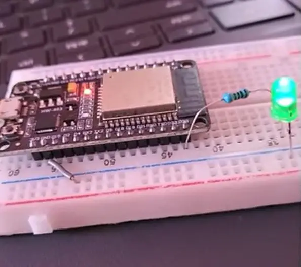
If you are starting with home automation then you can start learning with this project. This project will teach you to control the status of an LED using an AWS management console. For this, you need to connect an LED to the GPIO 23 of the ESP32 module with a 560-ohm resistor. And you can control the LED status from any part of the world.
First, you need to create a thing and a policy on the AWS management console. When the LED control is set to 1 on the console, the LED glows and a message is sent to the serial monitor. While setting the control to 0, the LED stops glowing along with a message on the serial monitor.
Home Automation with Amazon AWS IoT Core & ESP32
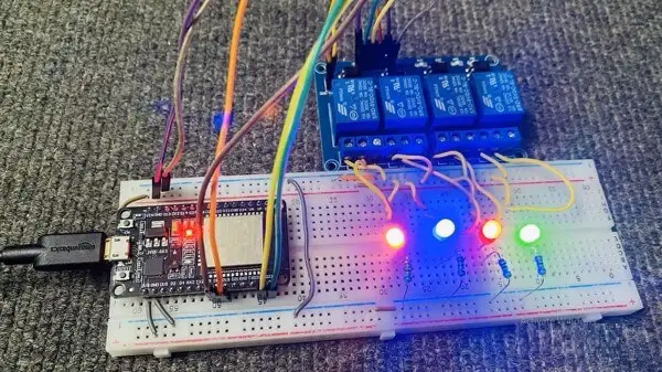
This project is an advanced version of the previous one. It uses a 4-channel relay module to control various home appliances in your home. Using this circuit diagram, you can power the module using a 9-volt DC adapter.
The voltage regulator converts it to 5 volts. The four pins of the ESP32 are used as the output. Now, to control the status of any lamp, select the corresponding topic and change its status. Inserting 1 will turn the lamp on, while 0 will turn the lamp off along with a message on the serial monitor.