Last updated on July 11th, 2025 at 02:44 pm
In this article, you will learn about the L298N motor driver module in detail. But first, we must answer some basic questions like what is a motor driver, why it is used in a circuit, what is an H-bridge configuration, etc.
Table of Contents
What is a motor driver module?

Image Source: sproboticworks
A motor driver module is a simple circuit used for controlling a DC motor. It is commonly used in autonomous robots and RC cars (L298N and L293D are the most regularly utilized motor driver chips).
A motor driver module takes the low voltage input from a controller like Arduino. This input logic controls the direction of DC motors connected to the driver. To put it in simple words, you can control the direction of DC motors by giving appropriate logic to the motor driver module.
The motor driver module consists of a motor driver IC, which is the heart of the module. The IC alone can control the DC motor, but using the module makes interfacing with Arduino easy.
Why do we need a motor driver module?
All microcontrollers operate on low-level voltage/current signals, unlike motors. For instance, the Arduino or PIC microcontroller can output a maximum voltage of 5V or 3.3V. But a decent DC motor needs at least 5V or 12V. Also, the output current limit of Arduino is relatively very low.
Hence the output of Arduino is not enough to power up the motors. To solve this problem, the use of a motor driver is essential. We bridge the gap between the Arduino and the motor by introducing a motor driver. To supply the voltage/current required to operate the motor, an external supply is connected to the motor driver module.
**Checkout this high current (3A, 55V) motor driver IC- a good alternative to L298N.
What is an L298N motor driver?

The L298N motor driver is based on the H-bridge configuration (an H-bridge is a simple circuit that lets us control a DC motor to go backward or forward.), which is useful in controlling the direction of rotation of a DC motor.
It is a high current dual full H-bridge driver constructed to receive standard TTL logic levels. It can also control inductive loads such as relays, solenoids, motors (DC and stepper motor), etc. An H-bridge schematic looks like this:

Image Source: Wikipedia
The direction of rotation of the motor depends upon the switch positions.

Image Source: Wikipedia
When S1 and S4 are ON and S2 and S3 are OFF, the left side of the motor terminal is more +ve than the other terminal. This causes the clockwise rotation of the motor.
When S2, S3 are ON and S1, S4 are OFF, the right side of the motor terminal is more +ve than the left terminal. This causes anticlockwise rotation of the motor.
The H-bridge configuration is commonly used to switch the direction of the motor. However, it can also be utilized to ‘brake’ the motor. This causes the motor to stop instantly as the motor’s terminals are shorted, or to let the motor ‘free rush’ to a stop (coasts), as the motor is viably separated from the circuit.
The table below sums up the activity, with S1-S4 corresponding to the diagram above:
| S1 | S2 | S3 | S4 | Result |
| 1 | 0 | 0 | 1 | Motor turn right |
| 0 | 1 | 1 | 0 | Motor turn left |
| 0 | 0 | 0 | 0 |
Motor Coasts |
| 1 | 0 | 0 | 0 | |
| 0 | 1 | 0 | 0 | |
| 0 | 0 | 1 | 0 | |
| 0 | 0 | 0 | 1 | |
| 0 | 1 | 0 | 1 | Motor Brake |
| 1 | 0 | 1 | 0 | |
| X | X | 1 | 1 | Short circuit |
| 1 | 1 | X | X |
NOTE: L298N has two such h-bridge circuits meaning you can control up to two DC motors using it.
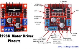
L298N motor driver module pinout
The L298N motor driver module consists of an L298 IC Dual H-bridge, 5V Voltage Regulator, resistors, capacitor, Power LED, and 5V jumper.

2 DC motor output pins, 12-volt external motor power supply, motor direction control pins (IN1, IN2, IN3, IN4), motor output enable pins (ENA, ENB), and a heat sink.
| VCC pin supplies power to the motor. Voltage anywhere between 5 to 35V can be applied. Remember, if the 5V-EN jumper is in place, you need to supply 2 extra volts than the motor’s actual voltage requirement, to run the motor at its maximum speed.
GND is the common ground pin. 5V pin supplies power to the switching logic circuitry inside the L298N IC. If the 5V-EN jumper is in place, this pin acts as output and can be used to power up the Arduino. If the 5V-EN jumper is removed, you need to connect it to the 5V pin on Arduino. ENA pins are utilized to control the speed of Motor A. Supplying this pin with HIGH logic makes the Motor A rotate, supplying it with LOW logic causes the motor to stop. Removing the jumper and connecting this pin to the PWM input let us control the speed of Motor A. IN1 & IN2 pins are used to control the direction of Motor A. If IN1 is HIGH and IN2 is LOW, Motor A spins in a certain direction. To change the direction, make IN1 LOW and IN2 HIGH. If both the inputs are either HIGH or LOW,Motor A stops. IN3 & IN4 pins are used to control the direction of the Motor B. If IN3 is HIGH and IN4 is LOW, Motor B spins in a certain direction. To change the direction, make IN3 LOW and IN4 HIGH. If both the inputs are either HIGH or LOW, the Motor B stops. ENB pin can be used to control the speed of Motor B. Supplying this pin with the HIGH signal makes the Motor B turn, supplying it LOW cause the motor to stop. Eliminating the jumper and interfacing this pin to PWM information let us control the speed of Motor B. OUT1 & OUT2 pins are connected to Motor A. OUT3 & OUT4 pins are connected to Motor B. |
The L298N IC comes in multi watt package which makes it difficult to use in basic prototyping circuits. Thats why the module of L298N is more popular than the IC itself.
Still, you can look at the pinout of the IC given below for learning purposes.
Pinout of L298N motor driver IC

| Pins | Name | Function |
| 1,15 | Sense A, Sense B | Between this pin and the ground, a sense resistor is connected to control the current of the load. |
| 2,3 | Out 1, Out 2 | Supply Voltage for the Power Output Stages. A non-inductive 100nF capacitor must be connected between this pin and the ground. |
| 4 | VS | Supply Voltage for the Logic Blocks. (A100nF capacitor must be connected between this pin and the ground.) |
| 5,7 | Input 1, Input 2 | TTL Compatible Inputs of the Bridge A. |
| 6,11 | Enable A, Enable B | TTL Compatible Enable Input: the L state disables the bridge A(enable A) and/or the bridge B (enable B). |
| 8 | GND | Ground |
| 9 | VSS | Supply Voltage for the Logic Blocks. (A100nF capacitor must be connected between this pin and ground.) |
| 10,12 | Input 3, Input 4 | TTL Compatible Inputs of the Bridge B. |
| 13,14 | Out 3, Out 4 | Outputs of the Bridge B. The current that flows through the load connected between these two pins is monitored at the pin. |
Features and specifications
Given below are the technical specifications of this module
| Specification | Value |
|---|---|
| IC supply voltage(VSS) | 4.5 V -7 V |
| Input low voltage | 0 V – 1.5 V |
| Input high voltage | 2.3 V – VSS(applied) |
| Motor channel | 2 |
| Operating voltage | 5 V |
| Continuous Current per Channel | 1 A |
| Power consumption | 36 mA (logic) |
| Peak Current per Channel | 2 A |
| Power connector | Pins (5 V) or Screw Terminals (7-35 V) |
| Power supply voltage(for motors) | upto 46 V |
| Dimensions(module) | 43 x 43 x 23 mm |
| Weight | 33 g |
L298N motor driver IC Datasheet
Click this link to view the DATASHEET.
You can find detailed information on L298N IC in the datasheet given above. Specifications and information like Absolute maximum ratings, Block diagrams, and suggested circuits can be found in the datasheet.
Schematic diagram
As you can see in the schematic below, the module has a 78M05 voltage regulator, 6 diodes, one LED, 2 capacitors, and one resistor.

Where to buy an L298N motor driver?
You can easily find this motor driver module in your local electronics store. For online purchases, we recommend this best deal on Amazon:
FAQs
Can L298N power a 12v motor?
Yes, the module can power a 12V motor as its maximum power supply voltage rating is 46 V.
What is ENA and ENB in L298N?
ENA and ENB are enabled pins on the L298N motor driver module, allowing you to control the speed of connected motors using PWM signals.
What is the power source of the L298N?
The power source for the L298N motor driver module typically comes from an external power supply. It can be a battery pack, DC power supply, or any other suitable power source that provides the required voltage and current for the motors being controlled.
Can L298N work with 3.3V?
The L298N motor driver is designed for higher voltages, typically starting from 5V. While it might operate with a 3.3V logic level, it’s not recommended as it could result in unreliable performance or potential damage to the module.
Can L298N control motor speed?
Yes, the L298N motor driver can control motor speed by adjusting the voltage and duty cycle of the PWM (Pulse Width Modulation) signal sent to its enable pins (ENA and ENB), thereby regulating the motor’s speed.
What is the voltage limit of L298N?
It operates within a voltage range of 5V to 46V.
nice