Last updated on March 27th, 2024 at 11:13 am
L293D is a basic motor driver integrated chip (IC) that enables us to drive a DC motor in either direction and also control the speed of the motor. The L293D is a 16-pin IC, with 8 pins on each side, allowing us to control the motor.
It means that we can use a single L293D to run up to two DC motors. L293D consists of two H-bridge circuit. H-bridge is the simplest circuit for changing polarity across the load connected to it.
There are 2 OUTPUT pins, 2 INPUT pins, and 1 ENABLE pin for driving each motor. It is designed to drive inductive loads such as solenoids, relays, DC motors, and bipolar stepper motors, as well as other high-current/high-voltage loads.

Table of Contents
L293D motor driver pinout

| Pin No. | Name | Function |
| 1 | Enable 1-2 | When this pin is given HIGH or Logic 1, the left side of the IC works and when it is low, the left side doesn’t work. |
| 2 | INPUT 1 | When this pin is given HIGH or logic 1, the output 1 becomes HIGH. |
| 3 | OUTPUT 1 | This pin is connected to one of the terminals of the motor 1. |
| 4,5 | GND | Should be connected to the circuit’s ground. |
| 6 | OUTPUT 2 | This pin is connected to one of the terminals of the motor 1. |
| 7 | INPUT 2 | When this pin is given HIGH or Logic 1, the output 2 becomes HIGH. |
| 8 | VCC2 | This is the voltage required to run the motor. IT can be greater than the IC voltage(VCC1). |
| 16 | VCC1 | It provides power to the l293D IC. So, this pin should be supplied with 5 V. |
| 15 | INPUT 4 | When this pin is given HIGH or logic 1, the output 4 becomes HIGH. |
| 14 | OUTPUT 4 | This pin is connected to one of the terminals of the motor 2. |
| 13,12 | GND | Should be connected to the circuit’s ground. |
| 11 | OUTPUT 3 | This pin is connected to one of the terminals of the motor 2. |
| 10 | INPUT 3 | When this pin is given HIGH or logic 1, the output 3 becomes HIGH. |
| 9 | Enable 3-4 | When this pin is given HIGH or Logic 1, the right side of the IC works and when it is low, the right side doesn’t work. |
Note: There are a total of 4 ground pins in L293D IC because it has to deal with heavy currents. So, we need a heat sink to reduce the heating and protect the IC from damage. When we solder these pins on PCB, we get a large metallic area between the grounds where the heat can be released.
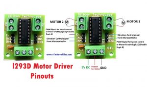
Pinout of L293D motor driver module

The image given above shows the pinouts of the L293D motor driver module. The function of each pin and port is also mentioned in the picture.
IN1, IN2, and IN3, IN4 are input pins used for providing a control signal from the controller to run the motor in different directions.
Specifications
Given below are the technical specifications of this motor driver IC.
| Specifications | Description |
|---|---|
| IC | Dual H-Bridge Motor Driver |
| Motor Control | Two DC Motors |
| Speed Control | Yes |
| Direction Control | Yes |
| Motor Voltage (Vcc2) | 4.5V to 36V |
| Maximum Peak Motor Current | 1.2A |
| Maximum Continuous Motor Current | 600mA |
| Supply Voltage (Vcc1) | 4.5V to 7V |
| Maximum junction temperature, TJ | 150-degree celsius |
| Separate Input | Logic Supply |
| Thermal shutdown | Automatic |
| Packages Available | 16-pin DIP, TSSOP, SOIC |
Working of L293D motor driver IC
There are 4 input pins for direction control in L293d. Pin 2,7 (1A and 2A) on the left side and pin 15,10 (3A and 4A) on the right of the IC.
The left-side input pins regulate the rotation of the motor connected across the left end and the right-side input pins regulate the motor on the right side. The motors are rotated based on the inputs provided across the input pins as HIGH or LOW signals.
Let’s take an example, a motor is connected on the left side output pins (pin 3,6). To control this motor, we have to provide an input logic to pin 2,7 (1A,2A).

- Pin 2 = HIGH and Pin 7 = LOW | Clockwise Direction
- Pin 2 = LOW and Pin 7 = HIGH | Counterclockwise Direction
- Pin 2 = LOW and Pin 7 = LOW | Idle (No rotation)
- Pin 2 = HIGH and Pin 7 = HIGH | Idle (No rotation)
Similarly, we can control the motor on the right side connected to the pin (11,14). For this, we need to provide HIGH and LOW input signals across pins (10,15).
- Pin 10 = HIGH and Pin 15 = LOW | Clockwise Direction
- Pin 10 = LOW and Pin 15 = HIGH | Counterclockwise Direction
- Pin 10 = LOW and Pin 15 = LOW | Idle (No rotation)
- Pin 10 = HIGH and Pin 15 = HIGH | Idle (No rotation)
L293D motor driver IC datasheet
Click this link to view the entire DATASHEET
You can find detailed information on L293D IC in the datasheet given above. Specifications and information like Absolute maximum ratings, Block diagrams, and suggested circuits can be found in the datasheet.
How to use L293D IC with Arduino UNO
Here’s a small project you can easily make using an L293D IC. The objective of this project is to control the state of the DC motor according to a predefined temperature limit.

To know more about this project click here: Temperature-controlled motor using L293D IC with Arduino
Where to buy L293D motor driver?

- This is a commonly used DC motor drive module, using a small current 293 chip DC motor driver chip.
- Using this chip you can use DC motors and power supplies of up to 10 Volts, that some pretty big motors and the chip can supply a maximum current of 600mA per channel.
FAQs
Can L293D control 2 motors?
Yes, the L293D can control up to two motors independently by utilizing its dual H-bridge configuration.
What is enable pin in L293D?
The enable pin in the L293D IC activates or deactivates motor output. A logic HIGH enables motor control, while a logic LOW disables it, offering convenient on/off functionality.
What does L293D stand for?
The “L” stands for “linear” because it’s designed to handle linear (analog) signals. The “293” signifies the model number, and the “D” indicates it’s a version of the chip.