Last updated on March 26th, 2024 at 04:20 pm
LM35 is an analog, linear temperature sensor. Analog means the output voltage of LM35 is analog in nature and linear means this output voltage varies linearly with the change in temperature.
The LM35 generates an output voltage directly in Celsius (Centigrade) without the need for additional calibration circuitry.
As the temperature goes up, the sensor produces a higher voltage output, and for every one-degree Celsius increase in temperature, the output voltage increases by 10 millivolts.

You can also watch this video for a better understanding:
Table of Contents
Pinout of LM35

1. +Vcc and ground provide power to the sensor. You can supply any voltage between 4v to 20v.
2. Vout OR signal pin gives the output voltage corresponding to temperature. The scale factor is .01v rise per degree Celsius.
Since LM35 is an analog device and gives analog output. It should be connected to the ADC aka analog to digital converter first to convert the output analog signal to Digital.

Now the good thing is Arduino has its own inbuilt ADC. So we need to just connect the Analog pin of Arduino to the Vout pin of LM35.
Another important factor to consider when using LM35 in your project is its low self-heating due to its drawing current which is only 60 uA.
Types of LM35
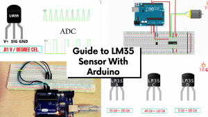
There are three different variants of LM35 available in a transistor package. LM35A, LM35C, and LM35D. The only difference is in the range of temperature measurements.

- LM35A can measure temperatures between -55 to 150 degree Celsius.
- LM35C between -40 to 110 and
- LM35D between 0 to 100 degrees Celsius. In this tutorial, I am using the LM35DZ variant.
Working
This is the functional block diagram of a typical LM35 which you can find in its datasheet. The three pins are shown below:

How is this circuit working?
1. It gives a temperature-dependent voltage output at the N terminal of the diode buffered by amplifier A2 to give output to the Vout pin.
2. These two transistors are used to create a bandgap voltage reference i.e. a constant fixed voltage reference regardless of temperature and power supply variations.

3. And this is the reason you can power LM35 using any voltage between 4 to 20v.
Now let’s see how to interface the temperature sensor with Arduino to print the surrounding temperature on the Serial monitor of Arduino IDE
Thermometer using LM35 with Arduino
Connect the sensor with UNO as shown in the circuit diagram below.
Circuit diagram

- +Vcc goes to 5 v pin of Arduino.
- GND goes to the GND pin of the Arduino.
- The signal pin goes to the Analog pin A0.

I have already mentioned that the analog output of the temperature sensor should be converted to digital-first and the scale factor is .01v rise per degree Celsius.
So, we are going to use an analog pin of Arduino to convert these analog output voltage values to digital values, and then by using a formula in the program, convert these digital values to the corresponding temperature.
Program
Copy this program to your Arduino IDE.
float Vout;
float Temp;
void setup()
{ Serial.begin(9600);
 }

 void loop()
 {
 SensorValue=analogRead(A0) ;
 Vout = (5/1023)* SensorValue
 Temp= Vout*100; /* Temp = (500/1024)*SensorValue
 Serial.print("Temperature in Degree Celsius = ");
 Serial.print(Temp);
 Serial.println();
 delay(1000);
 }
Code explanation
First, the value from analog pin A0 is stored in the SensorValue variable.
Then by using this formula the analog value is converted to degree Celsius: Temp= SensorValue*(500/1024)
How this formula is calculated?
- Suppose we are getting a value of 65(SensorValue) on the Serial monitor from the Vout pin of LM35.
- We know 1023 corresponds to 5v in Arduino. So 65 will correspond to (5/1024)* 65 and this will give us the output voltage. OR Vout= (5/1024)* SensorValue
- To convert this voltage to temperature in degrees Celsius, we will use the scale factor of .01V rise per degree Celsius.
- Temperature rise by 100 degrees Celcius gives 1V. So the input voltage(Vout) should give Temp = Vout*100 = (500/1024)* SensorValue. And this is the surrounding temperature in degrees Celsius.
- For example: If the voltage is 0.3V, then the temperature is: Temp = 30°C
Connect the Arduino burn cable to your laptop, select the COM port, and upload the code. Now open the serial monitor. The room temperature gets printed onto the serial monitor. Try to bring the hot iron close to the surface of LM35 and observe the change in temperature.
Temperature-controlled DC fan project
Here’s a small project you can easily make to control the state of the DC motor according to a predefined temperature limit. What this means is that as soon as the temperature rises to a certain value, the DC motor will start running. Please keep in mind that we are not controlling the motor speed here. It is just state control.
For this small project apart from the Arduino UNO and LM35 temperature sensor, you will also need a motor driver L293D, a 6-12v DC motor, and an external power supply.
Circuit diagram
Here are the circuit connections for the same:

Now, this circuit has a Motor driver IC to control the motor. So we are going to use the L293D Module or L293D IC. You can also use L298N for the same purpose.
NOTE: To make things easier I using the L293D Motor driver module instead of IC. But if you are a beginner I will recommend using L293D IC.
Program
Upload this program to your Arduino board:
float Vout;
float Temp;

void setup() {

  Serial.begin(9600);
  pinMode(8,OUTPUT);
  pinMode(9,OUTPUT);

  }

void loop() {
  Vout=analogRead(A0) ;
  Temp= (Vout*500)/1023 ;
  if(Temp>=40)
  {
    digitalWrite(8,HIGH);
    digitalWrite(9,LOW );
   }

  else{ digitalWrite(8,LOW);
        digitalWrite(9,LOW );
        }
  Serial.print("Temperature in Degree Celsius = ");
  Serial.print(Temp);
  Serial.println();
  delay(1000);

}
Code explanation
- First, set digital pins 8 and 9 as OUTPUT pins
- Store the value from analog pin A0 to the Vout variable. Then by using the formula explained earlier convert this value to degree Celsius.
- Now we are going to use the if command to set the condition to turn the motor on. So if the temperature is >=40 then digital write 8-pin high and 9-pin Low
- Else in any other case, digital write both the pins LOW.
What this program does is that, when the temperature is less than 40 degrees Celsius, the motor will not run but as soon as the temperature reaches 40 degrees, it starts running.
Note: Upload this code and power the Arduino from an external 12 v Adapter.
1) Open the serial monitor. As you can see in the left image given below, the temperature is 30 degrees celsius which is less than 40 degrees, The motor is not rotating.


2) Increase the temperature by bringing heated iron close to the surface of LM35 and observe the motor state.
FAQs
What does LM in LM35 mean?
The LM stands for “Linear Monolithic” temperature sensor. Linear because the output voltage of the sensor changes linearly with temperature and Monolithic because all the electronic components inside the sensor are fabricated on a single piece of silicon.
What is the difference between LM35 and a thermistor?
The output voltage of an LM35 changes linearly with a change in temperature whereas in a thermistor, its resistance changes non-linearly with temperature. To use a thermistor with Arduino, you need an additional resistor.
By using this code, can I move two dc motor instead of one?
Hi John,
Yes you can but you will have to add the new motor and arduino digital I/O pins to the other side of the L293D(IN3 , IN4 , OUT3, OUT 4, EN2 etc.) And change the code accordingly.
sir my lm35 dz is showing tempreature 148 at room tempreature and it is not fluctuating after i take hot spoon or any thing near it.
i had tried many codes from google but the output is same .what can i do now
Hi Siddhant,
Maybe the sensor is broken. Replace it with a new one and then get the readings.