Last updated on February 11th, 2025 at 11:32 am
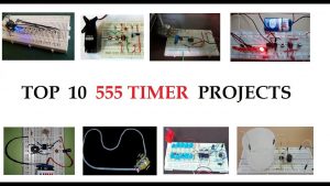
Are you a beginner looking for the top 555 Timer projects to build? Then you crashed at the right webpage!
Projects in this list are selected very carefully by keeping each and every aspect in mind. Please remember that the projects in this list are selected mainly to brush up on your basics. And not merely based on the complexity involved.
So when you go through these projects, don’t judge on the basis of difficulty and application only. These projects will give you a good idea of 555 timer never-ending applications. The link to each project is given below the respective project’s summary.
List of 555 timer projects
10. Dark Sensor built using 555 Timer
To build a Dark Sensor circuit using a 555 timer and LDR which turns on the buzzer in the presence of dark.
This project is built using an LDR with the timer. The Buzzer is used as an output indicator in this project.
When light falls on the LDR, the timer processes this signal and sends logic 0 to the output i.e. the buzzer. And as soon as the light goes off, no light falls on the LDR. Then 555 timer processes this signal and sends logic 1 to the output i.e, the buzzer. This way buzzer produces a beep sound in the absence of light or in the presence of dark.
Components list
- 555 Timer
- LDR(Light dependent resistors)
- Connecting Wires
- Buzzer
- Battery 9v
- Breadboard
- Capacitors 100uf and .01uf
- Resistors 4.7k and 47k
Link to the project site: 555 Timer-based Dark Sensor
9. Servo tester using 555 timer, BC547, and two Pushbuttons
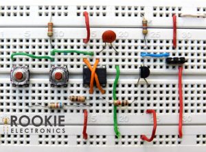
As the name of the project itself suggests, this circuit was built to check whether your servo motor is working or not.
One pushbutton causes clockwise rotation whereas the other pushbutton causes anticlockwise rotation of the Servo motor. Apart from the 555 timer, you also need a BC547 transistor and a couple of resistors to build this Servo tester.
Components list
- Resistors
- Battery 9v
- Continous Roatation Servo
- Connecting Wires
- 2 Push Switches
- BC 547 Transistor
- 100nF Capacitor
Link to the project site: Servo Tester Using 555 Timer
8. Tone Generator using 555 timer and potentiometer
555 timer generates signals as you rotate the potentiometer causing a series of tone generation from the Speaker.
To build this tone generator, you need a potentiometer along with a couple of Electrolytic and Ceramic capacitors.
Components list
- Potentiometer 1 Mohm
- Connecting Wires
- 9v Battery
- Breadboard
- 1k resistor
- Speaker
Link to the site project: Tone Generator from 555 Timer
7. Water Level Indicator using 555 Timer and a Buzzer
As soon as the level of water rises to a specific height, Buzzer starts beeping.
Two metal contacts, probe, or wire is placed at different heights. One is always placed at the bottom of the container whereas the other is placed at a position where as soon as the water reaches, the buzzer starts beeping. We have to change the position of this contact according to our needs.
As soon as the water reaches the required level, the circuit closes i.e. the current starts flowing through these contacts. The buzzer indicates this by producing sound.
Components list
- Breadboard
- Connecting Wires
- Resistors
- 9v Battery
Link to the project site: Water Level Indicator
6. LED chaser using 555 timer and 4017 IC
10 LEDs connected at the outputs of 4017 IC through 555 timer starts flashing one by one as soon as the circuit is powered on.
Since LEDs glow one by one, it seems like they are chasing each other.
Components list
- CD 4017 Ic
- Connecting Wires
- LED Lights X 10
- Breadboard
- Resistors 470R, 1k, 47k
Link to the project site: Led Chaser
5. Electronic Piano built using 555 Timer
Each pushbutton plays a different tone when it is pressed. Thus, this overall setup gives a feeling of a Demo Piano built using a 555 timer IC!
10 pushbuttons are used in this project, i.e., you get 10 different tones. You can also change the default tone of each pushbutton by rotating the potentiometer.
Components list
- 10 Pushbuttons
- 10 Resistors, 1k ohm each
- Potentiometer
- 9volt battery
- Buzzer
- Capacitors
Link to the project site: Electronic Piano Using 555 Ic
4. Continuity Tester built using 555 timer
To detect the break-in continuity of a wire by producing sound through the buzzer.
Continuity Tester is a simple electronics tool that indicates the continuity of a circuit when that circuit is connected between the connecting probes of the Continuity Tester Circuit.
Components list
- Buzzer
- Capacitors 100uf and .01uf
- Potentiometer
- 9volt battery
- Resistors 4.7k and 47k
- Connecting probes
Link to the project site: Continuity Checker from 555 IC
3. Electronic dice using 4017 IC, 6 LEDs with 555 Timer
Make this electronic dice circuit where each of the six LEDs indicates a number. When the pushbutton is pressed, a random LED flashes.
A potentiometer is also connected to change the regular reoccurring results.
Watch this video to see “Electronic Dice” in action!
Components list
- CD4017 IC
- Potentiometer 10k
- Capacitor 10uf
- 1K Resistors X 2
- LEDs
- Pushbutton X 6
- Battery
Link to the project site: Digital Dice using 555 Timer
2. Stun Gun using 555 timer
This powerful stun gun is made using two transformers, a couple of capacitors, a 555 timer, and a transistor.
Link to the project site: Stun Gun using 555 timer
1. Line Following Robot
Make a Line-following Robot using three 555 timers, 2 Ldrs, and 2 BD3904 transistors.
This robot follows the white line on a black background.
Watch the video above to see “Line Follower” in action!
Components list
- 555 Timer X 3
- Ldr X 2
- BD3904 Transistor X 2
- Connecting Wires
- 10 uf X 3
- 1N4148 Diode
- Arduino UNO
- Battery
- DC geared motor X 2
Link to the project site: Line following robot using 555 timer