When you’re getting started with electronics, it’s easy to make mistakes that seem small but can completely stop a circuit from working.
In this article, we’ll look at common circuit mistakes and overlooked details that every electronics beginner should know.
Beginner Electronics Mistakes
1. Physical Pin Numbers and GPIO Numbers Are Different
If you’re just getting started with microcontrollers, one thing you need to be careful about is the difference between physical pin numbers and GPIO numbers.
The physical pin number tells you the position of a pin on a connector or header, while the GPIO number identifies the actual input/output pin of the microcontroller that you program. These numbers aren’t necessarily the same.
For example, on one ESP32 development board, GPIO 23 might be available on header pin 18, while on another version, the same GPIO could be available on header pin 20.
So, when making connections, don’t rely only on a pin’s physical position. Always check the pinout diagram for your exact development board and make sure you’re using the correct GPIO number in your code.
2. Components With the Same Package Can Have Different Pinouts
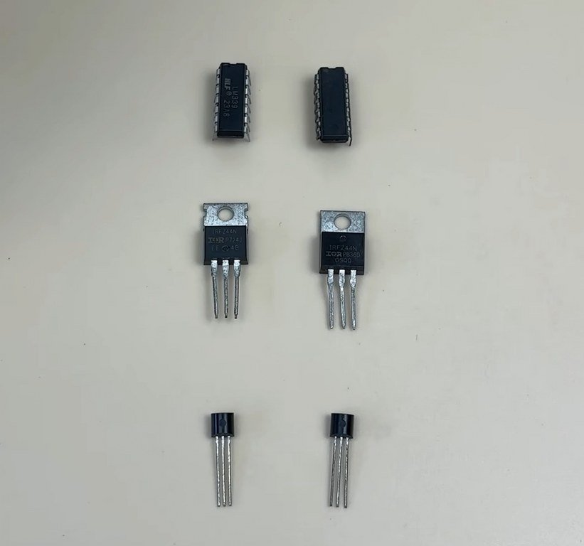
Two components can look almost identical but have completely different pin arrangements and electrical characteristics.
For example, take these two NPN transistors, BC547 and 2N904. Both come in a TO-92 package and look almost identical, but their emitter, base, and collector pins are arranged differently.
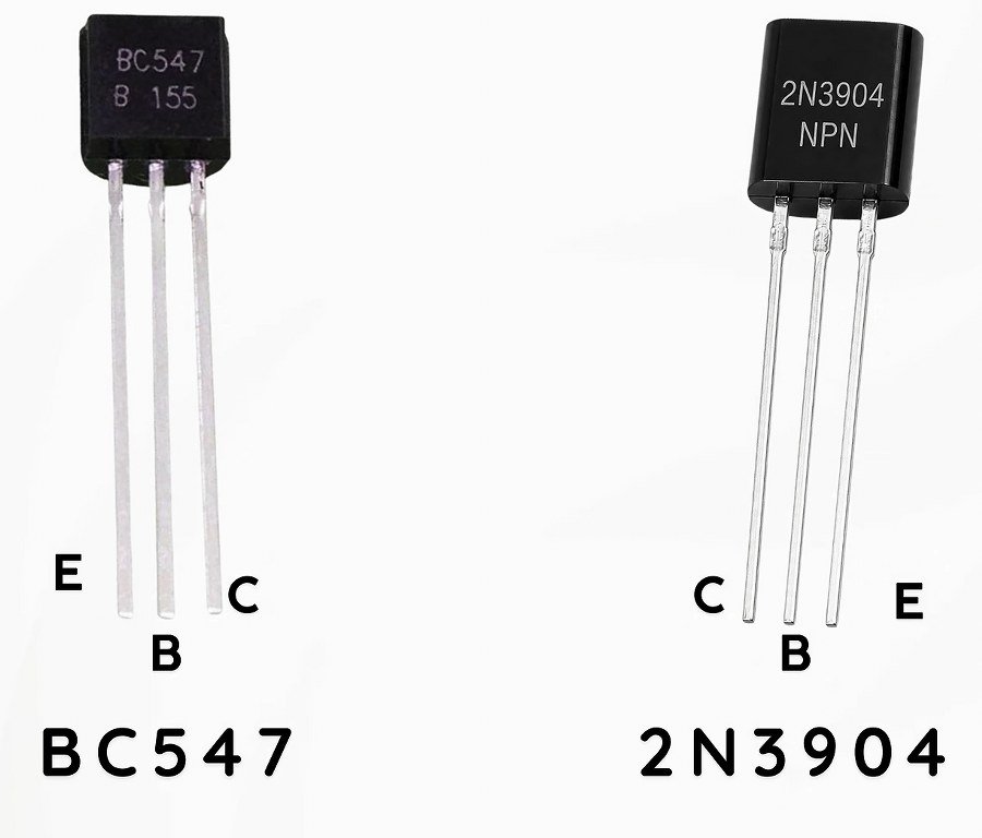
Now, if you replace one transistor with another without checking its pinout, your circuit might not work as expected, even though the replacement seems to fit perfectly.
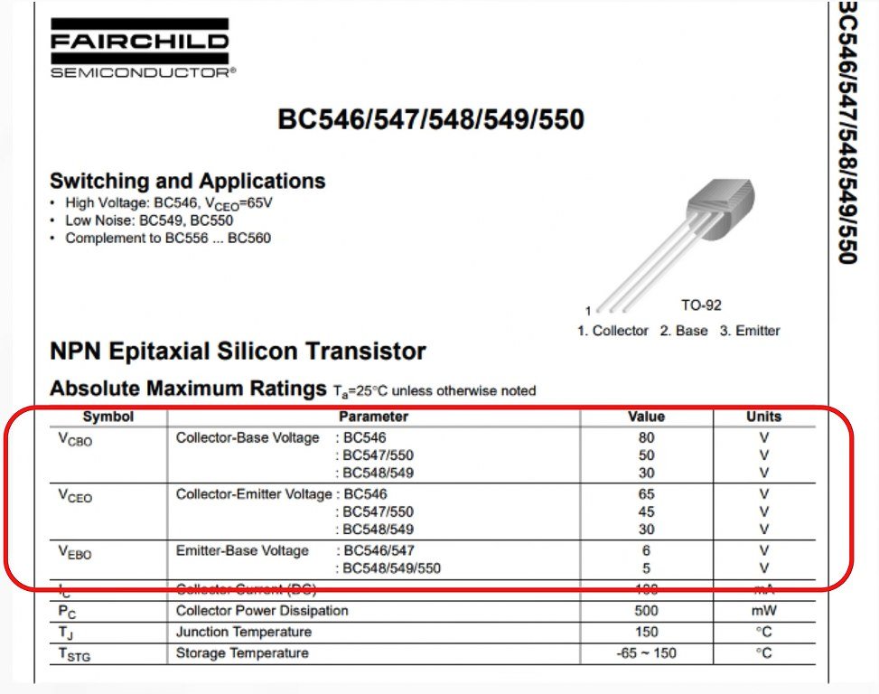
And even if two components have the same pinout and are from the same family, they can have different electrical ratings.
So, always check the datasheet before replacing a component.
3. IC Orientation and Pin Numbering
Just like electrolytic capacitors and diodes have polarity, ICs also need to be placed in the correct orientation. If you insert an IC the wrong way around, it may not work and could even get damaged.
To identify the correct orientation, look for a small notch or dot on the IC package. These markings help you locate pin number 1.
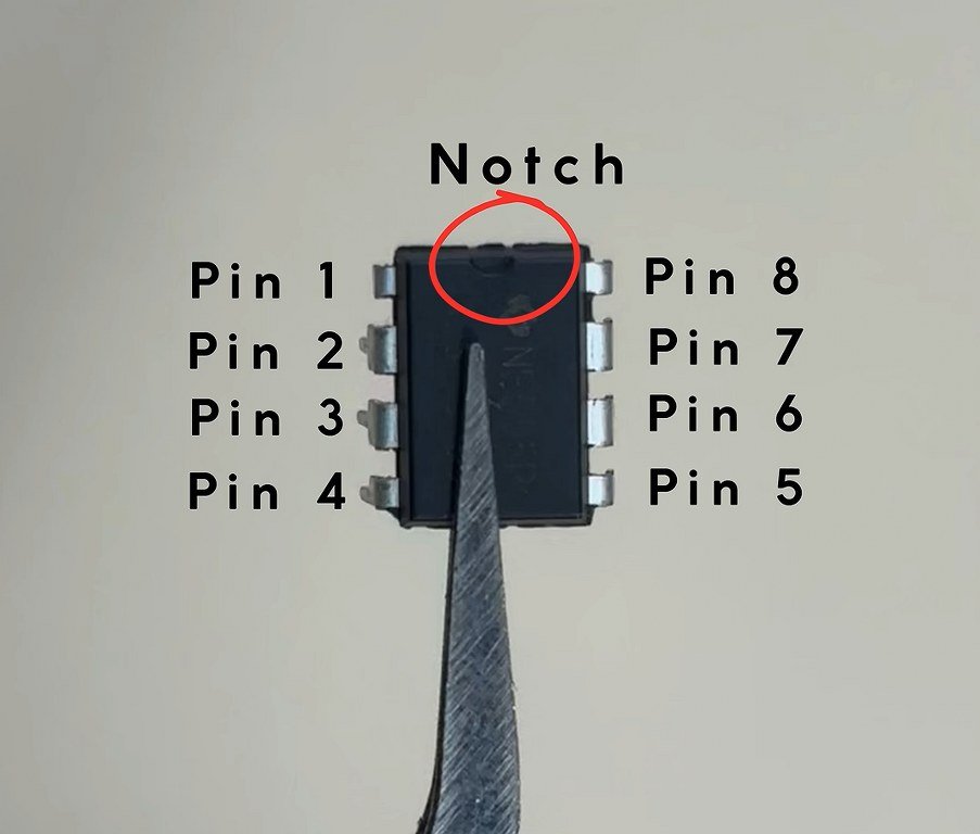
For a typical DIP IC, when you’re looking at it from the top with the notch facing upward, pin 1 is on the top left. The pin numbers then increase down the left side, continue from the bottom right, and move upward along the right side until you reach the last pin.
The easiest way to remember this is that the pin numbers increase counterclockwise when viewed from the top.
4. Forgetting the Common Ground
When looking at circuit diagrams, you’ll often find GND symbols connected to different components. These symbols indicate that those points are electrically connected to the same ground net, even if no wires are shown between them.
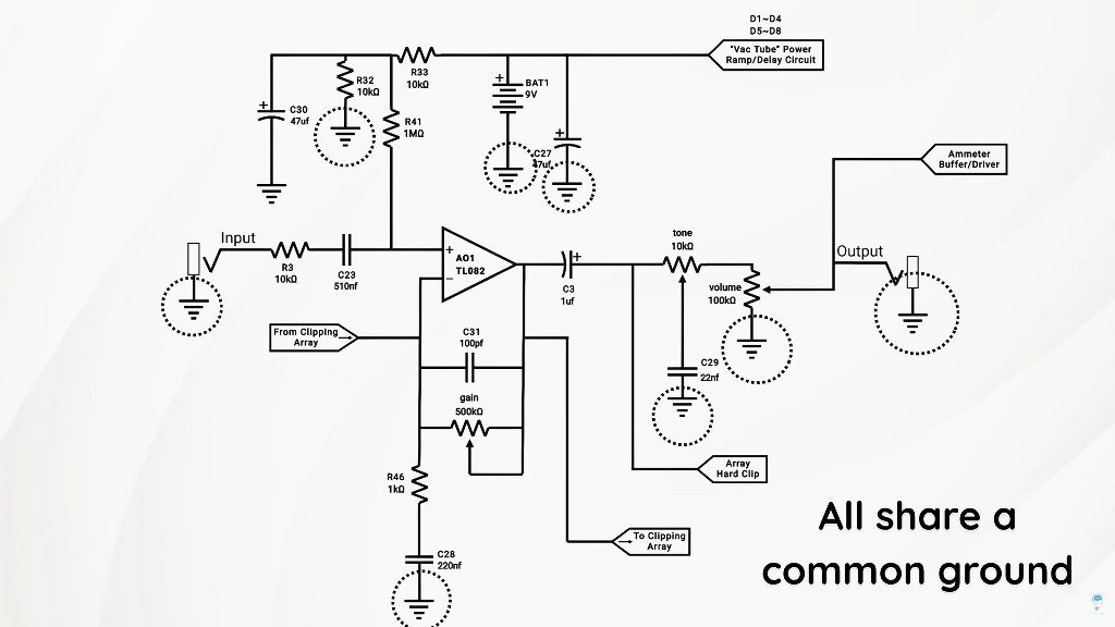
But why is this connection necessary?
The reason is simple: voltage is always measured between two points. So, when one device sends a signal to another, the receiving device needs a common voltage reference to understand whether that signal is HIGH or LOW. Connecting their grounds together provides that reference.
For example, in this circuit, an ESP32 is used to control a DC motor through a transistor.
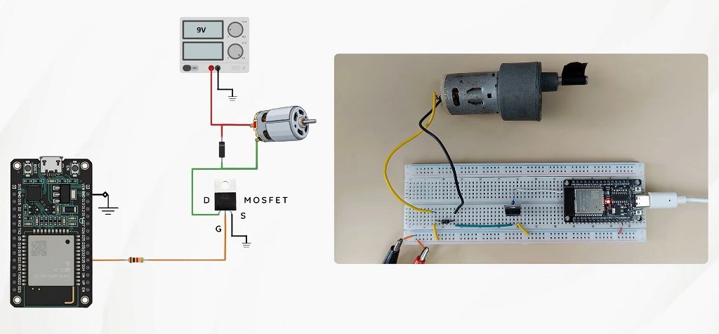
The motor is powered separately from a power supply, while the ESP32 is powered through USB. If the ESP32’s GND pin and the negative terminal of the motor’s power supply aren’t connected together, the transistor’s control signal may not work as expected because the ESP32 and transistor circuit don’t share a common voltage reference.
By connecting these grounds together, we give the ESP32’s GPIO signal and the transistor a common reference, allowing the transistor to respond correctly to the signal.
The same principle applies when connecting sensors. For example, if several sensors are connected to an Arduino, they can share a common ground with the board.
This is a very common practice in electronics.
Just remember that this applies when the circuit requires a shared ground reference. Isolated circuits are designed differently.
5. Connecting 5 V Signals to 3.3 V Devices
Before using a sensor or module with your development board, always check their voltage compatibility.
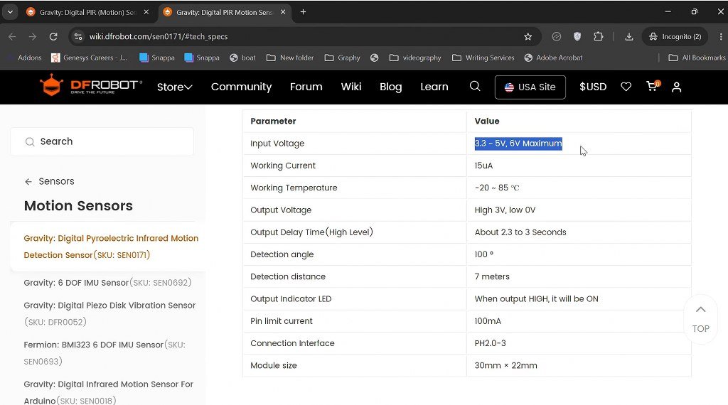
For example, the ESP32 operates with 3.3 V logic, and its GPIO pins aren’t 5 V tolerant.
Let’s say you want to connect an HC-SR04 ultrasonic sensor module with the ESP32.
The sensor operates at 5 V, and its Echo pin also outputs a 5 V signal. Therefore, you should avoid connecting the Echo pin directly to a GPIO. Instead, use a voltage divider to reduce the signal to a safe 3.3 V level before connecting it.
Another important point to remember is that a module’s power supply voltage and output signal voltage are two different things.
6. Supply Voltage Doesn’t Always Equal Its Output Voltage
A module’s power supply voltage and output signal voltage are two different things.
If a sensor module is powered with 5 V, you cannot assume its output signals will be either 5 V or 3.3 V.
Just as we saw in the previous HC-SR04 example, you need to check what voltage the module actually produces on its output pins.
Similarly, some modules include level-shifting circuitry to make their signals compatible with different logic levels, while others don’t.
So, always check the module’s documentation and pin specifications instead of assuming that the output voltage is the same as the supply voltage.
7. Ignoring GPIO Current Limits
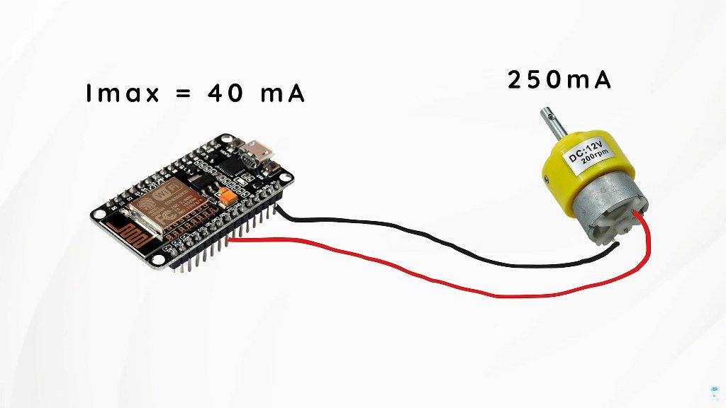
There’s a reason we use motor drivers and transistors to switch loads like motors and relays. These components can draw more current than a microcontroller’s GPIO pin can safely supply.
But beginners often overlook this and connect components directly to GPIO pins without checking their current requirements. Exceeding the pin’s limits can damage the microcontroller.
Another thing to keep in mind is the overall current limit of all the GPIO pins combined.
This happens more often than you might think. We sometimes connect too many devices to a board, causing the total current draw to exceed the microcontroller’s limits.
For example, the Arduino Uno R3’s ATmega328P specifies 40 mA per I/O pin and 200 mA through its VCC and GND pins as absolute maximum ratings. But these maximum ratings aren’t recommended operating currents, so you should always stay within the recommended limits specified in the datasheet.
8. Assuming Every MOSFET Can Be Fully Turned ON by a Microcontroller
Not every MOSFET can be fully turned ON by a microcontroller, even if you connect its gate to a HIGH signal.
To understand why, remember that a MOSFET’s gate-source voltage controls how well it conducts between its drain and source. Different MOSFETs require different gate-drive voltages to achieve a low ON resistance and turn ON fully.
This is where logic-level MOSFETs come in. They’re designed to achieve a low ON resistance with relatively low gate-drive voltages, making them suitable for microcontroller projects.
Now, even among logic-level MOSFETs, you need to check whether the device works properly with your particular microcontroller.
For example, a MOSFET that achieves a low ON resistance with a 5 V gate drive may not perform as well when driven by an ESP32’s 3.3 V output.
A good example is the IRFZ44N versus the IRLZ44N. Both are N-channel MOSFETs, but the IRLZ44N is designed for logic-level drive with a VGS of 4–5 V to turn on fully, while the IRFZ44N requires a VGS of 10 V.
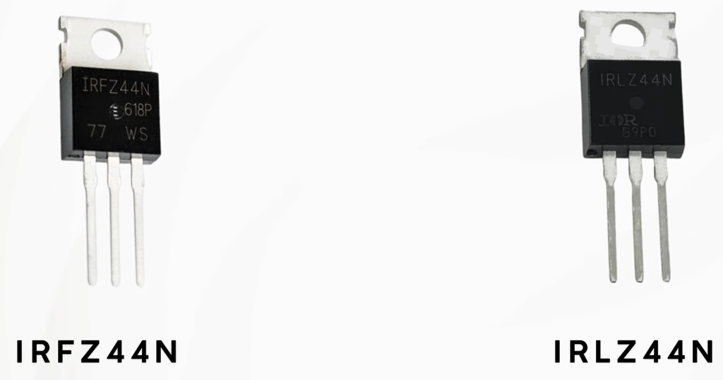
So, you can use the IRLZ44N with an Arduino, and to some extent with an ESP32 as well, but the IRFZ44N cannot be used properly with either of them.
Lastly, don’t confuse the gate threshold voltage, VGS(th), with the voltage required to fully turn the MOSFET ON.
The threshold voltage only indicates when the MOSFET begins conducting a small current. It doesn’t mean the MOSFET can efficiently drive your load.
So, before choosing a MOSFET, check its datasheet and look for the ON resistance, RDS(on), specified at a gate-source voltage your microcontroller can actually provide.
9. Inductive Voltage Spikes: Using a Flyback Diode
Components like motors, relays, or solenoids can produce voltage spikes when switched off.
These components contain coils, which store energy in a magnetic field when current flows through them. When you suddenly switch off the current, the magnetic field collapses, and the coil generates a voltage that opposes the change in current.
This can produce a sudden voltage spike that damages the transistor or other components in your circuit.
To prevent this, a diode called a flyback diode is connected across the coil of a DC relay or a brushed DC motor.
Now, when the transistor switches off, the diode provides a path for the coil current to circulate, helping suppress the voltage spike.
Look at this relay switching circuit using the ESP32.
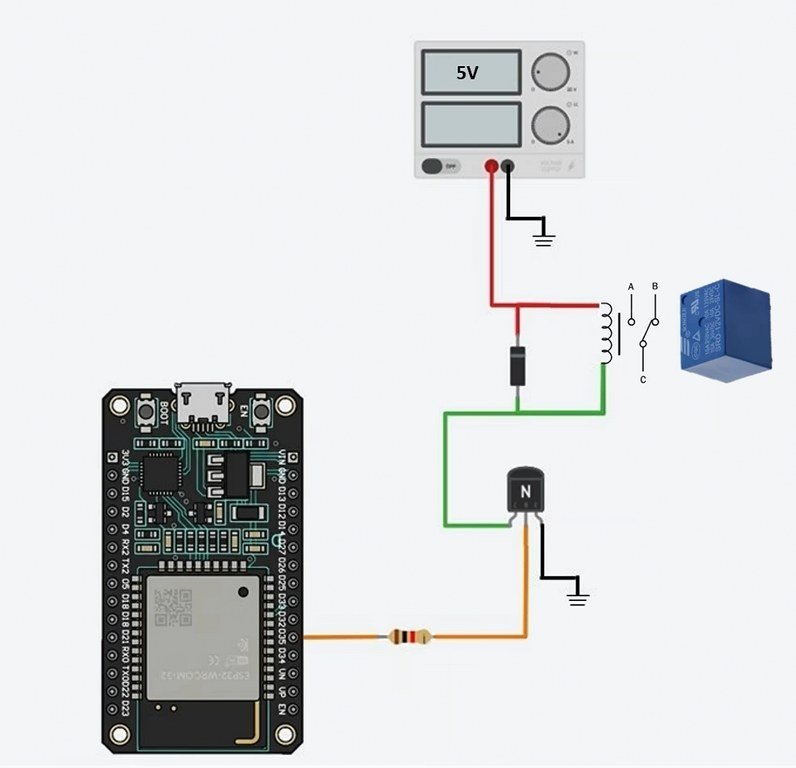
Notice the diode connected across the relay coil.
Let’s remove it.
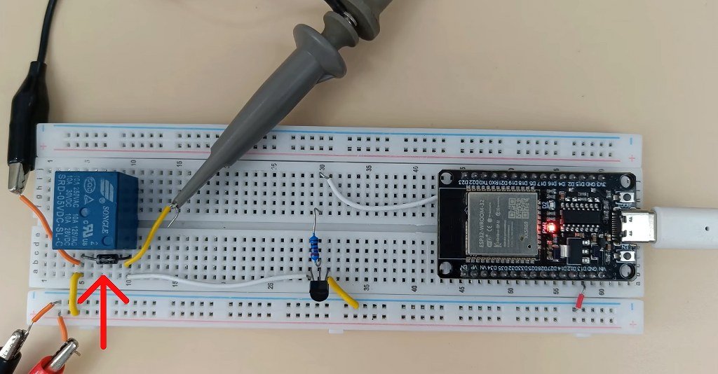
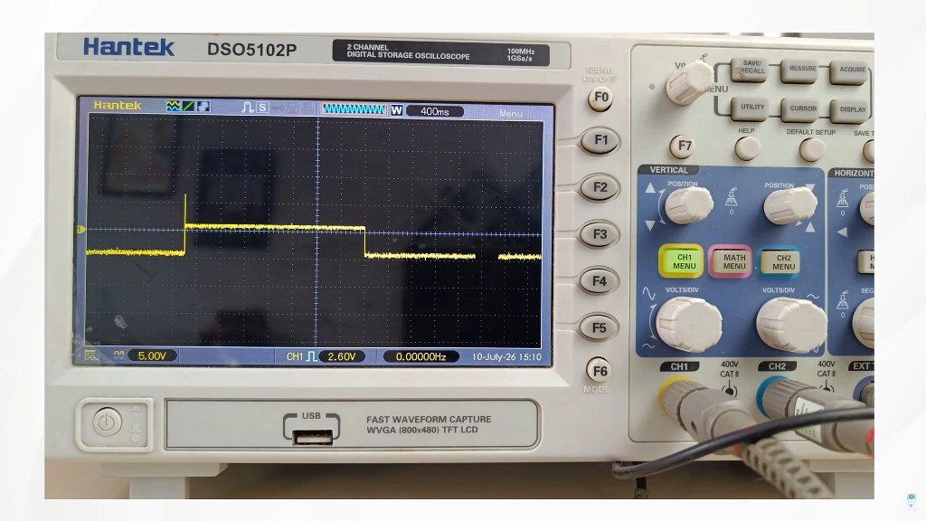
When the relay turns off, its coil suddenly collapses and produces a high voltage spike in the opposite direction. That spike can easily damage the transistor, MOSFET, or even the ESP32 controlling the relay.
Now let’s connect the diode again.
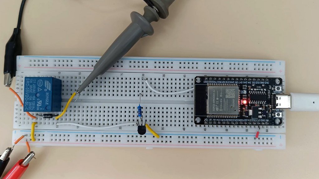

This time, when the relay switches off, the diode gives that stored energy a safe path to circulate through the relay coil. Instead of reaching the ESP32, the energy safely dies out inside the coil.
There’s one more place you must have seen a diode: in a DC motor control circuit. A motor also contains a coil, so when you suddenly switch the motor off, it produces the same kind of voltage spike.
That’s why you’ll often see a diode connected directly across the motor terminals.
This diode is called a flyback or freewheeling diode, and you’ll almost always find one across relays, motors, and other inductive loads.
10. Decoupling Capacitors Should Be Placed Close to the IC
When designing a circuit, choosing the right capacitor is important, but so is its placement. This is especially true for decoupling capacitors.
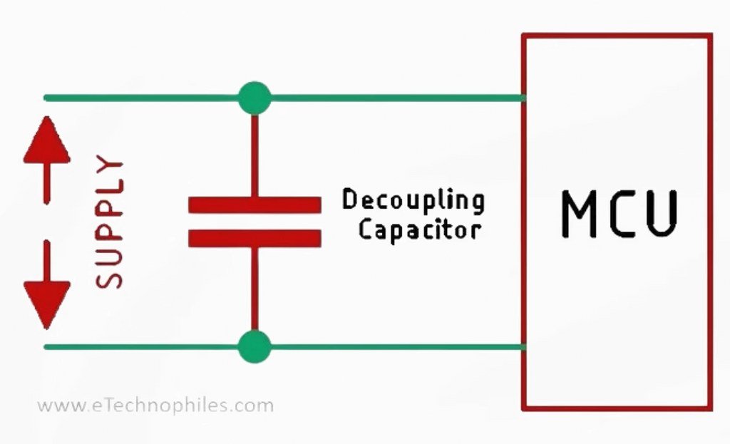
A decoupling capacitor’s job is to keep the supply voltage stable when an IC suddenly draws more current. It provides a local source of charge and helps reduce noise and voltage fluctuations on the power supply.
But if you place the capacitor too far away from the IC’s power pins, the extra wire length adds inductance, making the capacitor less effective at handling rapid changes in current.
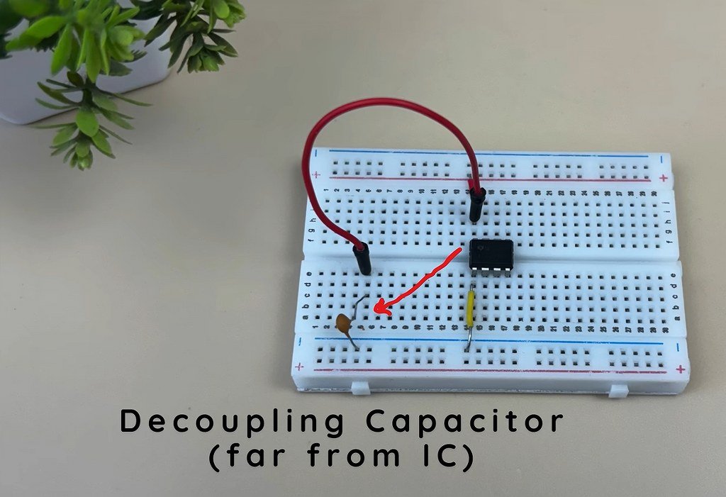
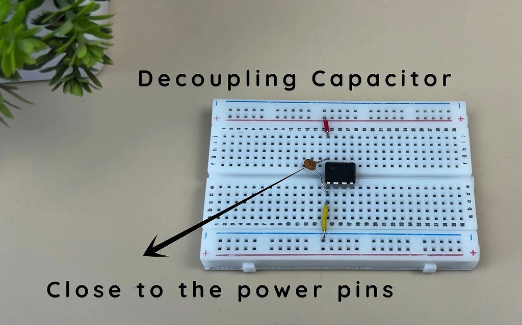
Even if you’re building circuits on a breadboard, always place the decoupling capacitor close to the power pins rather than connecting it through long jumper wires.
That’s why in circuit boards, you’ll always find them as close as practical to the IC’s power and ground pins, keeping the connections short.
11. Ground Doesn’t Always Mean 0 Volts
We usually consider ground to be 0 volts. But it isn’t necessarily at 0 volts relative to every other point in a circuit.
To understand this, first remember that voltage is always measured between two points. A multimeter, for example, measures the voltage difference between where you place the red probe and where you place the black probe.
In circuits, we choose one point as our reference and call it ground. We assign that point zero volts and measure other voltages relative to it.
Think of it like sea level, which we use as the reference point for measuring altitude.
For example, in this circuit, the negative terminal of the power supply is connected to GND. So, if we measure between GND and the positive terminal of a 5 V supply, we’ll read 5 volts.
Now, consider a circuit powered by a dual supply of +12 V and -12 V. If the middle point is used as ground, one power rail sits at +12 V while the other sits at -12 V relative to ground.
But here’s the interesting part: you could choose the -12 V rail as your reference instead. In that case, the former ground would be at +12 V, and the upper rail would be at +24 V.
The actual voltage differences between the three points haven’t changed; we’ve simply changed our reference.
Lastly, don’t confuse circuit ground with earth ground.
Circuit ground is just the local 0 V baseline inside your device, like a flashlight, smartphone, or Arduino. It floats along with the device and has zero connection to the physical planet. In some devices, circuit ground may be connected to earth ground.
On the other hand, earth ground is part of an electrical safety system. It is literally a copper rod driven into the earth outside your house.
12. Breadboard Power Rails
Now, let’s look at two easy-to-miss things about breadboard power rails that can cause problems in your circuit.
First, on some breadboards, the positive and negative power rails are split in the middle. This means that even if you connect your power supply at one end, the other half of the rail might not receive power.
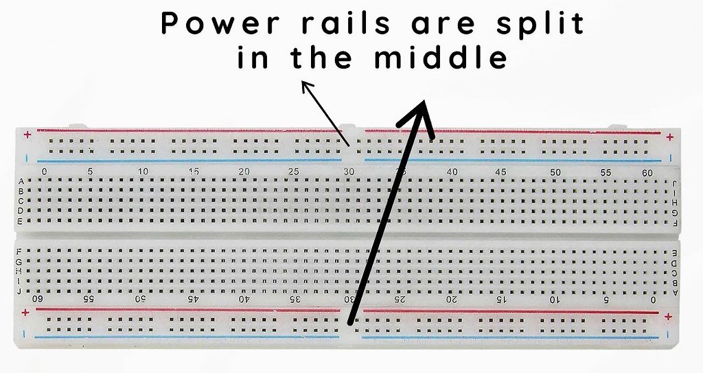
So, always check whether your new breadboard has split rails, and if it does, connect the sections using jumper wires.
Another thing to watch out for is the polarity markings on the power rails.
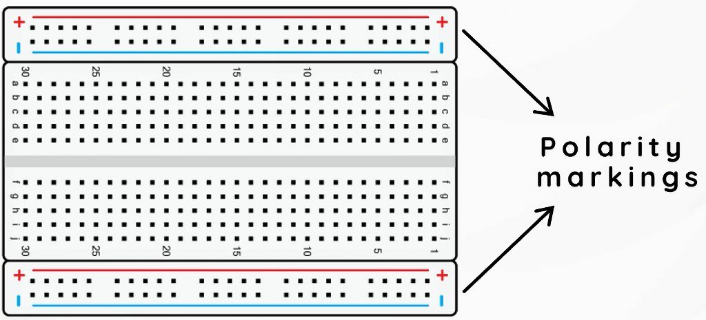
When building a circuit, I usually connect the power rails on both sides of the breadboard so I can power the entire board from a single supply connection.
But here’s where you need to be careful: the positive and negative markings are reversed on opposite sides.
If you connect the outer rails together and the inner rails together assuming the markings are the same, the positive supply can end up connected to a rail marked negative on the opposite side.
So, the markings may say negative, but that rail is actually carrying positive voltage.
13. Confusing Active-HIGH and Active-LOW Signals
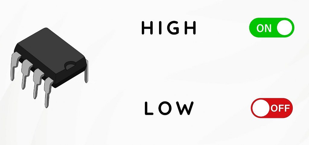
As a beginner, you might assume that setting a pin HIGH will turn something ON, and setting it LOW will turn it OFF.
But that’s not always how it works.
It actually depends on whether the signal is active-HIGH or active-LOW.
With an active-HIGH signal, the function is activated when the signal goes HIGH. But with an active-LOW signal, the function is activated when the signal goes LOW.
Look at the pinout of the 74HC595, for example. You’ll notice that two pins, Output Enable and Shift Register Clear, or MR, have bars over their names, indicating that they’re active-LOW signals.
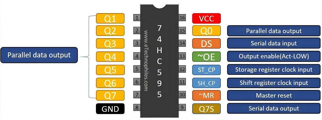
When Output Enable is set to LOW, the IC’s outputs are enabled. When it’s HIGH, the outputs are placed in a high-impedance state.
Similarly, when Shift Register Clear is set to LOW, the internal shift register is cleared. When it’s HIGH, the register can operate normally.
So, they are doing what they’re supposed to do when a LOW signal is given.
You might also see active-LOW signals indicated by a # symbol or a suffix like _N. For example, RESET_N usually indicates an active-LOW reset signal.
14. Forgetting a Pull-Down Resistor on a MOSFET Gate
When using a MOSFET as a switch in your microcontroller projects, one small component you shouldn’t overlook is a pull-down resistor.
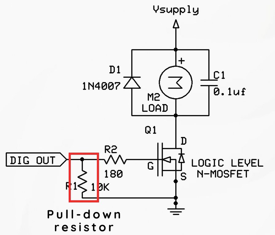
A microcontroller’s GPIO pin doesn’t always drive the MOSFET’s gate HIGH or LOW. For example, during startup or reset, the pin may be in a high-impedance state, meaning it isn’t actively controlling the gate voltage.
If there’s no pull-down resistor, the gate can be left floating, which may cause the MOSFET to turn ON unexpectedly during startup or reset.
To avoid this, connect a resistor between the gate and ground. This pulls the gate voltage LOW whenever the microcontroller isn’t driving it, helping keep the MOSFET switched OFF.
A 10 kΩ resistor is a common starting point for many switching circuits.
Another reason you should connect a pull-down resistor is that a MOSFET’s gate behaves somewhat like a capacitor and can store electrical charge.
Suppose you’re switching a MOSFET at a high frequency, say 100 kHz, as you might in a switching power supply. When the MOSFET turns OFF, the charge stored at its gate needs to be discharged.
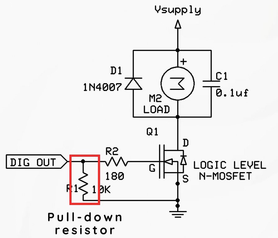
If there’s no proper path for this charge to escape, the gate voltage may not fall quickly enough, and the MOSFET might not turn OFF completely before the next switching cycle.
A pull-down resistor provides a path for this stored charge to discharge toward ground, helping the gate voltage fall LOW when the driving signal isn’t actively controlling it.
15. Ignoring Switch Bounce
When connecting a push button to a microcontroller, you might expect the signal to change cleanly from LOW to HIGH every time you press it.
But in reality, mechanical switches can produce several rapid transitions when their contacts open or close. This is called switch bounce.
Because of this, one press might register as multiple presses because the microcontroller detects these rapid transitions as separate inputs.
To prevent this, you can use a technique called debouncing.
This can be done in software by ignoring rapid changes for a short period, or in hardware using components such as resistors and capacitors.
16. Always Test Components
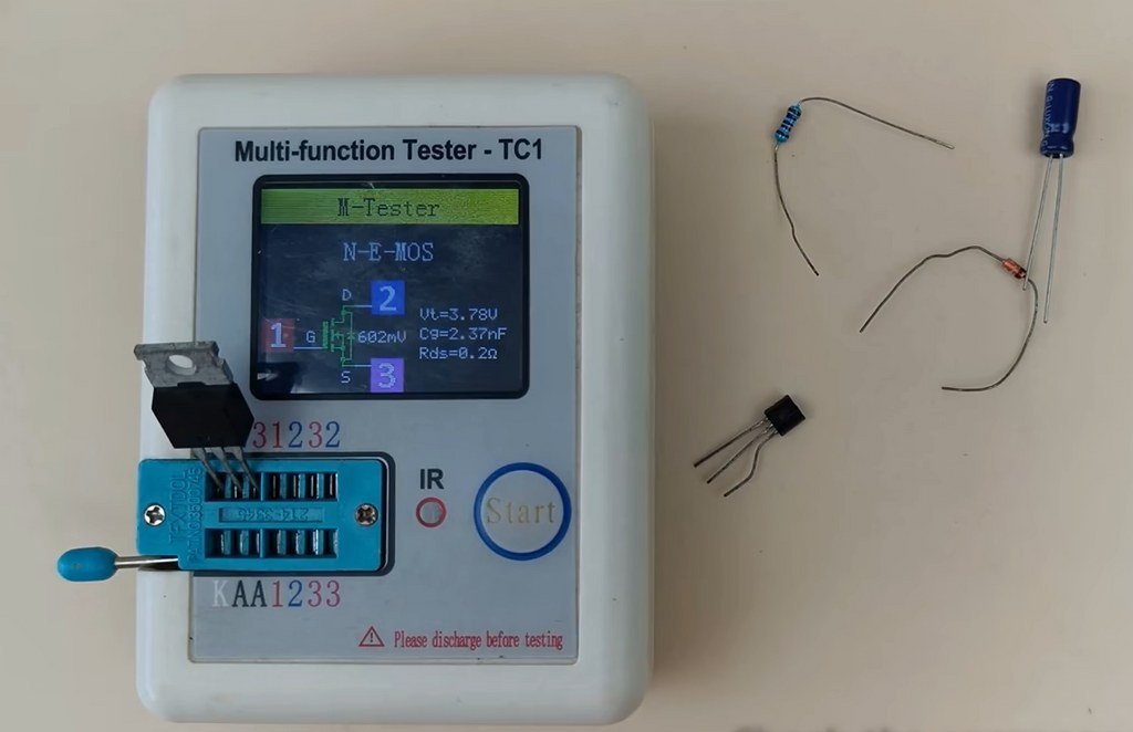
Before building a new circuit, the very first thing you should do is test your components.
I can’t remember how many times I’ve spent time trying to figure out why a circuit wasn’t working, only to realize much later that the problem was a faulty jumper wire.
For example, before using a jumper wire, you can set your multimeter to continuity mode and check whether there’s a proper electrical connection between its two ends.
Similarly, before powering the circuit, you can use your multimeter to check loose breadboard connections, damaged switches, or faulty components that are difficult to spot just by looking at them.
Also, before placing components like resistors or capacitors, don’t just rely on the markings. Always check their values before using them.
