
Last updated on January 6th, 2026 at 11:22 am
If you’re just starting out with electronics, DIY repairs, or even just curious about how things work behind the scenes, learning to use a multimeter is one of the best skills you can pick up.
Let’s say your TV remote stops working. Is the battery dead? A multimeter can tell you.
Fixing a lamp that’s flickering? Use the multimeter to check if power is reaching the bulb.
Here’s the cool part:
You don’t need to be an electrical engineer to use one. You don’t even need to know every single feature. In this guide, we’ll cover the essential stuff — the stuff that every beginner should know to feel confident using a multimeter.
We’ll break it down step by step:
By the end of this guide, you’ll be reading values like a pro and using your multimeter for all kinds of basic tests — safely and correctly.
Table of Contents
Parts of a digital multimeter
Before you can start measuring anything, it’s important to understand the basic parts of your digital multimeter. Most models, even the budget-friendly ones, follow a very similar layout.
Here are the main components you should know:

Display (Screen)
The display shows your measurement results — voltage, current, resistance, etc.
It may also show units like V, mV, A, Ω, or special symbols like “OL” (which stands for “open loop” or overload).
Rotary Dial (Quantity and Range selector)
Note: Learn basic multimeter symbols and their functions.
The rotary dial is used to select what type of measurement you want to take. Just rotate the dial to select the measurement type, such as DC voltage, resistance etc.
Apart from selecting the quantity to measure, you can also select the range for DC/AC voltage, resistance, and current. In most multimeters:

- DC voltage- There are 5 ranges: 200 mV, 2V, 20V, 200V, and 600V, as shown below.
- AC voltage-There are 2 ranges: 200 V, 600V(1000V in some multimeters).
- Resistance-There are 5 ranges: 200Ω, 2kΩ, 20kΩ, 200kΩ and 2MΩ.
- Current- There are 5 ranges: 200 uA, 2mA, 20mA, 200mA and 10A.
For example, if you select the 200 Ω range, it can measure resistance up to 200Ω with precision. It cannot measure resistance more than this value in this range. The multimeter will display ‘O.L’ or ‘1’ in this case.
Similarly, for 2kΩ, it can measure resistance between 0Ω and 2kΩ with precision. Though it will still measure and display the value lower than 200Ω in this range, the resolution(decimal places) will be lower.
Buttons (if available)
Some multimeters include extra buttons, depending on the model.
Common ones include:
- Hold: Freezes the current reading on the screen
- Backlight: Turns on the screen light
- Range: Lets you manually set a measurement range instead of using auto-range
If your multimeter doesn’t have buttons, that’s completely fine for basic use.
Probes (Test Leads)
Multimeters come with two probes:
- Black probe: Always goes into the COM (common) port
- Red probe: Goes into different ports depending on what you’re measuring
Each probe has an insulated handle and a pointed metal tip for contact with the test points.
Ports / Terminals
You’ll usually see three ports at the bottom of the multimeter:
- COM: Common ground – the black probe is always inserted here
- VΩmA: Used for most measurements including voltage, resistance, and low current
- 10A: Used for high current measurements (usually above 200mA)
Make sure the red probe is connected to the correct port based on what you’re testing. Using the wrong port could damage the multimeter or blow an internal fuse.
Auto range VS Manual
Some multimeters are auto-ranging — you just select the type of measurement, and it picks the best scale automatically.

Others require manual range selection, so you need to choose the closest voltage/resistance/current range based on what you’re expecting.

I will stick to the manual one in this tutorial as it is more common.
Looking for the right multimeter for you? Read this article, “Best Multimeters for Beginners“
How to use a multimeter for basic measurements?
Battery voltage measurement
One of the first things you can do with a multimeter is check if a battery still has charge. This is not only useful but also the easiest way to practice using your multimeter.
You can test any battery type using this method as long as it has two terminals(positive and negative). Let’s measure the voltage of an AA battery.

1. Set the dial
- Turn the rotary dial to DC Voltage (V— or V⎓).
- Select 2 V, since the voltage of an AA battery is around 1.5V. You can select 20V as well since the voltage of most batteries (AA, AAA, 9V, 12V) are below this. But results will be less precise in this case.
2. Connect the Probes
- Black probe goes into COM.
- Red probe goes into VΩmA (voltage port).
3. Touch the battery terminals
- Place the black probe on the negative (-) side of the battery.
- Place the red probe on the positive (+) side.
4. Read the display
- A new AA or AAA battery should read around 1.5V.
- A 9V battery should read close to 9V.
- If the reading is much lower (like 1.1V for AA or 7V for a 9V battery), it means the battery is weak or almost dead.
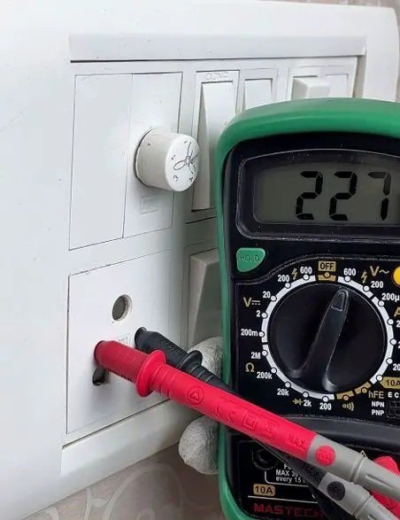
Measuring AC mains voltage
Using a multimeter, you can easily check if an outlet is live or whether it’s giving the correct voltage.
Read the in-depth article on A.C. mains voltage test using a multimeter.
Important safety note: AC mains voltage can be dangerous. Only attempt this if you’re careful and confident. Always hold the insulated part of the probes and never touch the metal tips while testing.
1. Set the dial
- Turn the rotary dial to AC Voltage (V~).
- Choose the highest range available (often 600V or 750V) — this keeps the meter safe even if the mains supply fluctuates.
2. Connect the Probes
- Black probe into COM.
- Red probe into VΩmA (the voltage port).
3. Test the outlet
- Insert the black probe into any of the two slot(except the Earth one).
- Insert the red probe into the other one.
- Be steady and avoid touching the metal parts.
4. Read the display
- In most regions, you’ll see around 220–240V AC (common in India/Europe/Asia).
- In the US, it should read around 110–120V AC.
- A much lower or unstable value could indicate wiring or power supply issues.
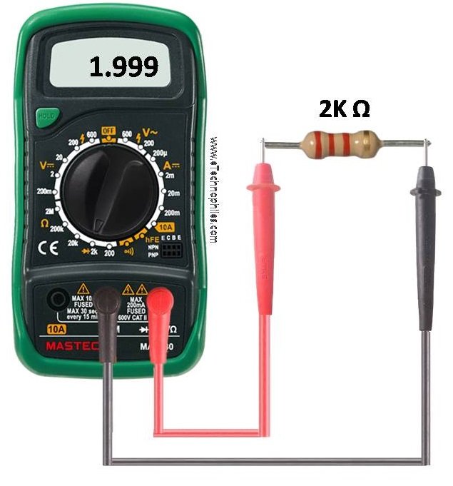
Measuring Resistance (Ω)
Resistance tells you how much a component or material resists the flow of electricity. It’s measured in ohms (Ω). You’ll use this to test resistors, check wires, or confirm if a component is open or shorted.
1. Set the dial
- Turn the rotary dial to the Ω (resistance) symbol.
- Choose a range higher than the expected value.
(For example, if you’re testing a 1kΩ resistor, set it to 20kΩ).
Note: If your multimeter shows OL, it means ‘open loop‘ or ‘over limit‘.
In resistance/voltage mode, when the display shows OL, it usually means the resistance is too high for the selected range — out of range. OR
In the continuity mode, it means there’s no connection between the two points you’re testing (an open circuit, broken wire, or blown fuse).
2. Connect the probes
- Black probe into COM.
- Red probe into VΩmA.
3. Take the measurement
- Touch one probe to each end of the resistor/component.
- The screen will show the resistance value in ohms (Ω), kilo-ohms (kΩ), or mega-ohms (MΩ).
Measuring DC Current (A, mA, or µA)
Unlike voltage or resistance (which you measure across a component), current is measured by placing the multimeter in series with the circuit. That means the current has to flow through your multimeter.
Read the in-depth article on measuring DC current using a multimeter.

1. Set the dial
- Turn the rotary dial to DC Current (A⎓, mA⎓, or µA⎓).
- If you’re unsure how much current to expect, start with the highest range (10A port) and then move down to mA or µA ranges for better accuracy.
2. Move the red probe
- Black probe → COM (as always).
- Red probe →
- 10A port if you expect high current (up to 10A).
- VΩmA port if you’re testing small currents (milliamps or microamps).
- The current limit for the VΩmA port will always be mentioned on the multimeter. When measuring the current value more than this, use the 10A port.
Please Note: Forgetting to move the red probe to the 10A port, in case you are measuring high current, is the #1 beginner mistake — it can blow the fuse inside your meter..
3. Break the circuit and insert the meter
- Current measurement requires you to open the circuit so the meter can be placed in line.
- Example: if you’re powering an LED with a battery, disconnect one side of the wire.
- Connect the multimeter in between that gap: one probe to the battery side, the other to the LED side.
4. Power the circuit and read the display
- Turn on the circuit.
- The display will now show how much current is flowing.
- For a small LED circuit, you might see something like 10–20mA.
Continuity test
Continuity mode is used to check if two points are connected electrically. Instead of just showing resistance in ohms, the multimeter beeps when there’s a good connection. This makes it quick and easy to test wires, fuses, switches, or PCB tracks.
Read this: Continuity test using a multimeter, follow-along guide.

1. Set the dial
- Turn the rotary dial to the continuity symbol (usually looks like a diode or a soundwave icon).
- On many meters, continuity and diode share the same setting.
2. Connect the probes
- Black probe → COM.
- Red probe → VΩmA port.
3. Test the multimeter first
- Touch the red and black probe tips together.
- The meter should beep, showing that the continuity mode is working.
4. Check your component or wire
- Place the probes at the two ends of the wire, fuse, or connection you want to test.
- If the circuit is closed (good connection), you’ll hear a beep.
- If it’s broken (open), there will be no beep, and the display may show “OL” (open loop).
Fuse protection inside the multimeter
Most digital multimeters have built-in fuses to protect both the meter and the user in case of mistakes — especially when measuring current.
When you measure current, the multimeter has to let electricity flow through it. If you accidentally connect the probes wrong (like putting them across a battery while in current mode), it creates a short circuit. This can damage the multimeter — or worse — if there’s no fuse.
The fuse acts as a safety barrier. If too much current flows, the fuse blows instantly and disconnects the circuit inside, saving the meter and preventing further accidents.
How to know if a fuse is blown?
- The multimeter shows “0.00” or nothing when measuring current.
- Other functions (like voltage and resistance) may still work fine.
- Some meters display a fuse warning symbol.
If the fuse inside your multimeter has blown, it’s essential to replace it. Learn how to do it yourself by watching this tutorial on YouTube.
Using a multimeter isn’t as hard as it looks. Start with simple checks like batteries or continuity, and you’ll quickly get the hang of it. Always stay safe, pick the right range, and connect the probes correctly. With just a little practice, you’ll be confident testing everyday electronics and fixing small issues on your own.
Useful guides on multimeter testing: