Last updated on February 12th, 2026 at 01:30 pm
There are three main synchronous motor starting methods: The first is by reducing the supply frequency, the second is by using an external motor, and the last is to start with damper windings.
The external motor drives the synchronous motor shaft. It can either be a pony motor, a DC motor, or an Induction motor. In this article, we will discuss all synchronous motor starting methods in detail. So, keep on reading till the end to know about all of them.
Table of Contents
Synchronous motor basics

Before we start synchronous motor starting methods, let us brush up on some basics of synchronous motors.
- A Synchronous motor belongs to the category of AC motors. But, a single supply source is not enough to start it. It requires a double excitation system to operate the motor.
- The stator of this motor carries a three-phase distributed armature winding, while the rotor contains the field winding.
- To find the synchronous speed of any machine, we use this formula:
Ns =(120xf)/p
f= frequency of the AC supply
p= number of stator poles
Ns= speed in RPM (rotations per minute)
Why is a synchronous motor not self-starting?
Armature & field excitation
A three-phase AC supply to the armature winding creates a rotating magnetic field in the armature. The speed at which the magnetic flux rotates is known as synchronous speed.
Now, at this instant, if we energize the rotor winding with a DC supply, it acts as an electromagnet with fixed polarity. So, the magnetic field is continuously rotating around an electromagnet, as shown in the figure.

The problem
Consider an instant when the opposite poles of the stator and rotor coincide. Due to the attraction property, the rotating field will try to pull the rotor along with it. So, the rotor tends to move with the magnetic field in a clockwise direction. But, due to the high rotor inertia, as it starts to rotate, the polarity of the magnetic field (aka stator) gets altered. So now, instead of an attractive force, a repulsive force starts acting. The rotating field will now try to push the rotor away from it.

The same cycle repeats during the next rotation of the magnetic field. As the torque acting on the rotor is pulsating, it is unable to move in either direction. Hence, the synchronous motor is not self-starting.
How can we make synchronous motor self-starting?
The main problem that prevents the motor from starting is the rotor inertia. If we can break this resting inertia, we can obtain a continuous (unidirectional) rotor torque. For this, we have different synchronous motor starting methods. All these methods follow the same principle, i.e., giving the rotor a starting torque. When the rotor achieves a speed close to the synchronous speed, exiting the field winding at this instant creates a magnetic locking, and the rotor rotates at synchronous speed.
Synchronous motor starting methods
The most common synchronous motor starting methods are:
- Supply frequency control
- Using an external motor
- Small pony motors
- DC motors
- Slip ring Induction motor
- Damper windings
Let us discuss these induction motor starting methods in a bit more detail.
Supply frequency control

As we saw above, the rotating magnetic field rotates at a very high speed. Hence, it is unable to break the resting inertia of the rotor. If this field rotates at a certain low speed, the rotor will accelerate and attain a synchronism with the magnetic field.
Using the above formula, we can vary the synchronous speed in two ways. Either by changing the supply frequency or by changing the number of stator poles. As the latter is not possible, we achieve a reduced speed by changing the supply frequency.
Using a Cycloconverter or a rectifier-inverter system, we can achieve a variable frequency AC supply. So during starting, these converters reduce the frequency of AC supply. When the rotor couples itself with the magnetic field, these converters slowly increase the frequency. And hence the motor runs at the rated frequency.
By using an external motor
In this case, the supply frequency is not varied. However, the shaft of the synchronous motor is coupled with an external electric motor. This external motor can either be a DC motor or an Induction motor.
The external motor rotates the shaft, and hence the rotor, near to the synchronous speed. It provides a starting torque to the rotor. At this instant, the field findings are exciting. And hence, the rotor couples itself with the rotating magnetic field.
When the motor starts running at synchronous speed, a switch detaches the external motor from the synchronous motor.
As a slip-ring Induction motor

The above synchronous motor starting methods use a squirrel cage rotor. But, this method requires a slip ring rotor. This method is similar to the rotor resistance starting of an induction motor. In this method, we add external resistance to the rotor via slip rings.
On giving a three-phase supply to the stator, the motor starts like a slip-ring induction motor. As the rotor accelerates, a switch cuts the external resistance in steps from the rotor circuit. By this time, the rotor attains a steady speed. So exciting the field winding pulls the rotor to synchronism.
This starting method gives two benefits:
- The presence of external resistance reduces the high inrush current during starting.
- The resistance also provides a good starting torque.
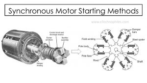
Using Damper windings
The prime function of the damper winding is to reduce hunting (oscillations) in the synchronous machine. But, it gives us an additional advantage. It makes the synchronous motor self-starting.

For this, the rotor structure requires some additions. The pole face of the rotor contains slots. Copper conductors are then inserted into these slots. End rings are attached at the end of the conductors to create a short circuit. The arrangement of damper winding looks similar to a squirrel cage induction motor.
The three-phase AC supply to the stator creates a rotating magnetic field. The rotating magnetic field links with the damper winding. So initially, the synchronous motor starts similar to an induction motor. The motor accelerates slowly and attains a sub-synchronous speed. Exciting the field winding at this moment pulls the rotor to synchronism.
When the motor achieves synchronous speed, the relative motion between the rotating field and damper winding becomes zero. Hence, no current flows in these windings.
In this way, the damper windings are present only at the starting and absent during the running time.